Control apparatus for internal combustion engine

a control apparatus and internal combustion engine technology, applied in the direction of electric control, muscle operated starters, instruments, etc., can solve the problems of power supply voltage, loss of ignition opportunity at the top dead center of initial compression, and function stoppage of ignition system, etc., to achieve superior startability, effective use of limited voltage, and guaranteed startability

Inactive Publication Date: 2009-03-05
HITACHI ASTEMO LTD
View PDF8 Cites 10 Cited by
  • Summary
  • Abstract
  • Description
  • Claims
  • Application Information

AI Technical Summary

Benefits of technology

[0032]According to the invention, because the driving of the fuel pump (i.e., the fuel supply processing) which consumes the largest amount of power is performed last in the startup control sequence, at the top dead center of the initial compression that requires an ignition output, it is possible to prevent the power supply voltage dropping below the minimum operating voltage of the control unit.
[0033]Namely, it is possible to prevent the electronic control

Problems solved by technology

Because of this, it is necessary to complete startup control using limited power.
Because of this, when the boosting of a condenser of a DC-CDI ignition system is started, the power supple voltage is reduced, and the problem sometimes arises that the power supply voltage drops below the minimum operating voltage of the CPU (Central Processing Unit) inside the ECU, so that the functions of the ignition system are stopped and the ignition opportunity at the top dead center of the initial compression is lost.
However, this solution is not preferable as it tends to lead to an increase in both the size of the generator and the cost thereof.
Because of this, when this system is applied to a fuel injection system, there is insufficient ignition output due to CPU voltage reduction.
Moreover, when the ignition system disclosed in Japanese Unexami

Method used


Image

  • Control apparatus for internal combustion engine
  • Control apparatus for internal combustion engine
  • Control apparatus for internal combustion engine

Examples


Embodiment Construction

[0048]An embodiment of the invention will be described with reference made to the drawings.

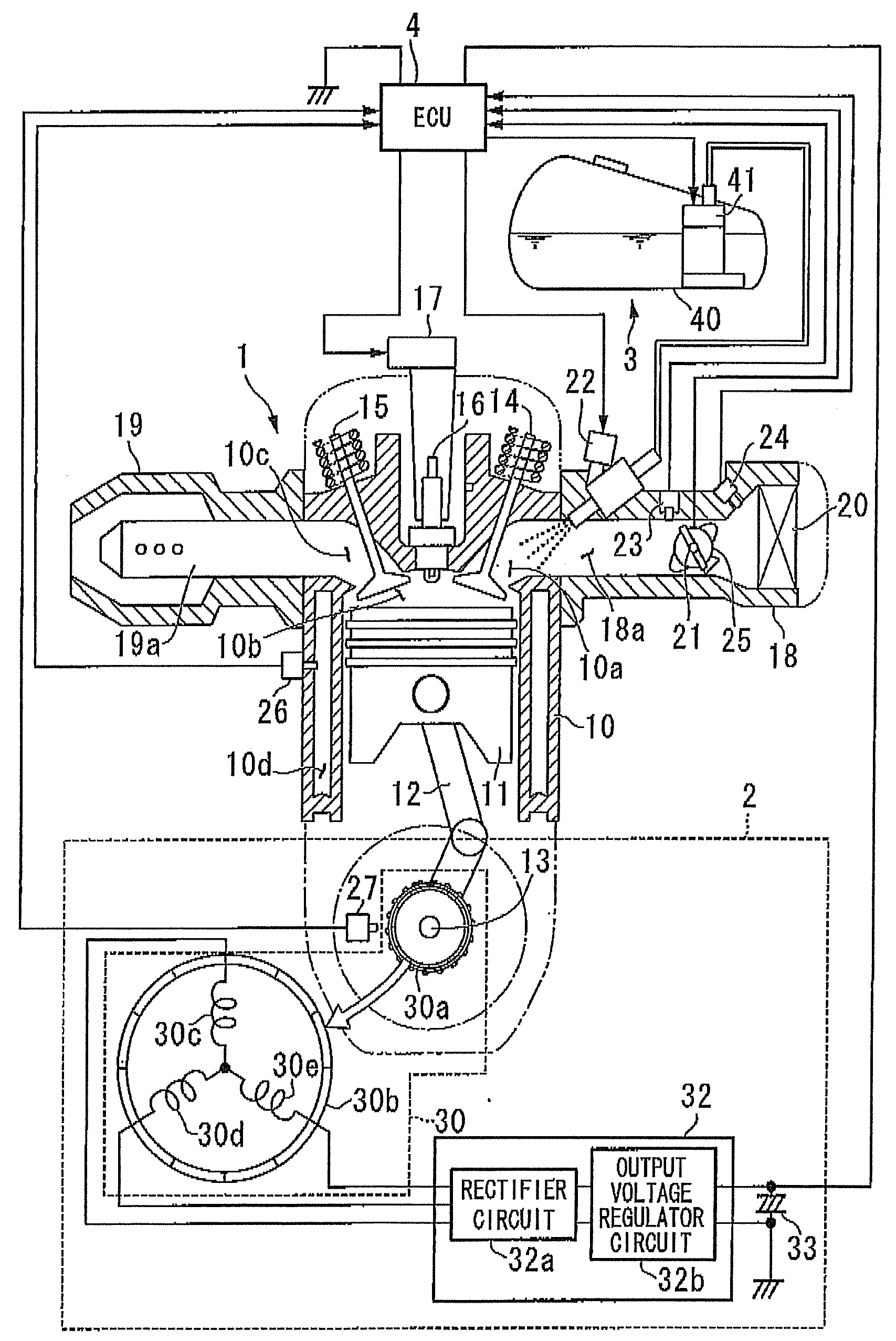
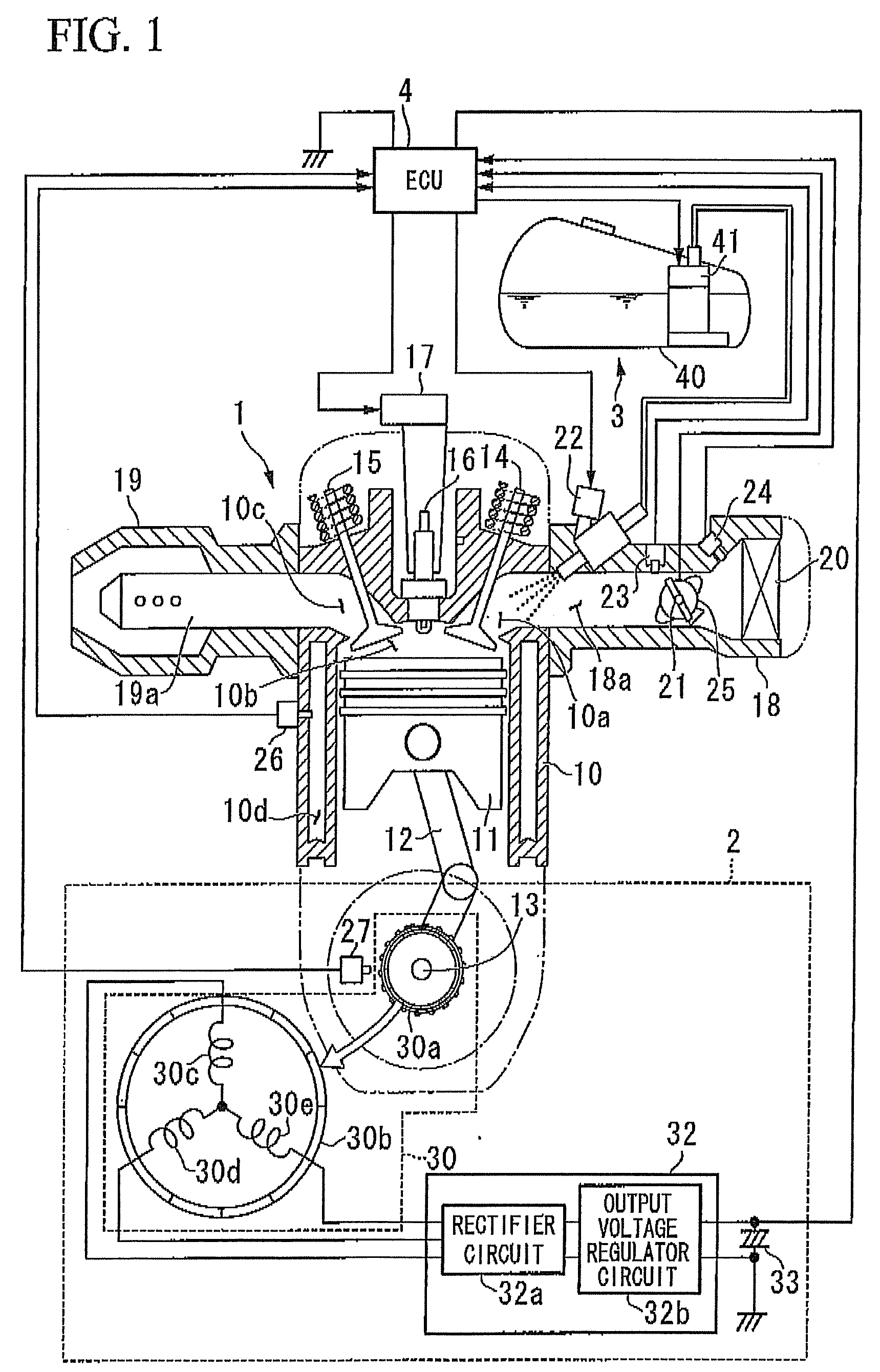
[0049]FIG. 1 is a structural schematic view showing an engine control system that is provided with the internal combustion engine control apparatus (referred to below as an ECU) of the embodiment.

[0050]As shown in FIG. 1, the engine control system of the embodiment is schematically formed by an engine 1, a power supply unit 2, a fuel supply unit 3, and an ECU (Engine Control Unit) 4.

[0051]A batteryless system that is not provided with a battery, bat instead performs engine startup by manual cranking (for example, by kick-starting) is described as an example of the engine control system of the embodiment.

[0052]The engine (i.e., internal combustion engine) 1 is a four-stroke single-cylinder engine, and schematically includes a cylinder 10, a piston 11, a conrod 12, a crankshaft 13, an intake valve 14, an exhaust valve 15, a spark plug 16, an ignition coil 17, an intake pipe 18, an exhaust pipe 1...


PUM


Abstract

A control apparatus for an internal combustion engine, includes: a fuel injection unit; an ignition unit; a crank angle detection unit; a fuel pump; a booster unit; an ignition discharge unit; and a control unit that controls the fuel injection unit, the ignition unit, and the fuel pump, that ascertains ignition timings based on crank signals output from the crank angle detection unit, and that performs a startup control sequence that is made up of fuel injection processing, voltage boosting processing, ignition processing, and fuel supply processing.

Description

BACKGROUND OF THE INVENTION[0001]This application is based on and claims priority from Japanese Patent Application No. 2007-223192, filed on Aug. 29, 2007, the contents of which are incorporated herein by reference.[0002]1. Field of the Invention[0003]The present invention relates to a control apparatus for an internal combustion engine, and, in particular, to a control apparatus for an internal combustion engine that is used to control a four-stroke engine serving as an internal combustion engine.[0004]2. Description of Related Art[0005]In a batteryless vehicle which travels by an internal combustion engine, electric power which is required at startup is fully provided by generated power from a generator that is driven by the rotation of the crankshaft of the internal combustion engine.[0006]Because of this, it is necessary to complete startup control using limited power.[0007]Accordingly, when a batteryless vehicle is being started up, it is desirable for power consumption to be k...

Claims


Application Information

Patent Timeline
IPC IPC(8): F02D45/00
CPCF02D37/02F02D41/009F02D41/062F02D41/3082F02D2041/2013F02P15/00F02N11/0862F02N2250/02F02P1/086F02P7/067F02N3/04
Inventor TOKUGAWA, KAZUHITOISHIKAWA, SHINICHISHIMOKAWA, TOMOOWACHI, KATSUAKICHIDA, SATOSHIUTSUMI, HIROYUKIAOKI, TAKAYUKI
Owner HITACHI ASTEMO LTD
Why Eureka
Try Eureka