
Plasma Processing Apparatus

a processing apparatus and plasma technology, applied in the field of plasma processing apparatus, can solve the problems of affecting the uniformity of the plasma, the actual guide wavelength does not completely agree with the design value, and the limitations of obtaining a uniform plasma, etc., to achieve the effect of reducing the size, flexibly coping, and facilitating the acquisition of uniform plasma

Inactive Publication Date: 2009-03-12
TOHOKU UNIV +1
View PDF15 Cites 45 Cited by
  • Summary
  • Abstract
  • Description
  • Claims
  • Application Information

AI Technical Summary

Benefits of technology

[0018]According to this invention, by providing means for adjusting a guide wavelength from the outside of a wave-guide path and by adjusting the guide wavelength of the wave-guide path by that means, the guide wavelength can always be maintained at an optimum value even if the conditions of use, such as the kind or pressure of gas or the microwave power, are changed. Therefore, it is possible to always generate a uniform plasma under the conditions of use over an extremely wide range. For example, it becomes possible to flexibly cope with even a process that is performed while continuously changing the conditions of use. Further, since the guide wavelength can be set to an optimum value even if there are various variations in the manufacture of plasma processing apparatuses, it is possible to easily obtain a uniform plasma even if a plasma processing apparatus has an increased size.
[0019]Further, according to this invention, by providing a plurality of waveguides and providing a plurality of dielectric plates for each waveguide, each dielectric plate is extremely reduced in size and thus the influence of thermal expansion of the dielectric plate is diminished and, therefore, gaps between the dielectric plates and adjacent members can be set small. Accordingly, even if a processing substrate has an increased area, there arises no such a problem that unintended plasma generation occurs in the gaps between the dielectric plates and the adjacent members.
[0020]Further, by providing a plurality of gas ejection holes in a partition member, the pitch between the gas ejection holes can be set small. Thus, a gas can be uniformly supplied over the entire surface of a processing substrate and, therefore, uniform processing with no unevenness is enabled. Further, since the partition member is made of a conductor and grounded, the microwave electric field is applied to the inside of the gas ejection holes. Therefore, the problem of generation of unintended plasma is not caused.

Problems solved by technology

Therefore, there is a problem that the conditions for obtaining a uniform plasma are limited.
Generally, the actual guide wavelength does not completely agree with a design value due to variation in size and permittivity of respective portions of wave-guide paths, variation in impedance of contact portions, variation in frequency, and so on and varies among apparatuses.
Particularly in large-size plasma processing apparatuses, waveguides are long and the number of slots per waveguide is large and, therefore, deviation in guide wavelength from an optimum value largely affects the uniformity of a plasma.
Therefore, there is a problem that even if the conditions of use are limited, it is difficult to always generate a uniform plasma and, particularly, the properties vary among the apparatuses.
It is obvious that these problems relating to the plasma uniformity will be actualized more and more in future.
When the dielectric plate expands to contact an adjacent member, the expansion is suppressed and thus an excessive stress is applied to the dielectric plate, so that there occurs a case where the dielectric plate is broken.
On the other hand, if this gap becomes greater than a certain degree (e.g. 0.1 mm or more), there arises a problem that unintended plasma generation occurs in the gap.
When a plasma is generated in the gap, not only the plasma generation efficiency is lowered due to a waste of microwave energy, but also the plasma uniformity and stability are significantly impaired.
Particularly in the film-forming process, uniform film formation cannot be carried out unless a gas necessary for the plasma processing is uniformly ejected over the entire surface of a processing substrate.
Therefore, there is a problem that uniform processing cannot be carried out and thus it can be applied only to a limited use.
However, since the dielectric plate is exposed to a strong microwave in the plasma processing, there is a case where unintended plasma generation occurs in the gas ejection holes formed in the dielectric plate.
However, high-level technique is required for uniformly forming a large number of such small holes in a dielectric plate made of a hard material such as ceramic or quartz and thus the cost and time is needed.
Further, there also arises a problem that a film adheres to the gas ejection holes to block them in the plasma processing.

Method used


Image

  • Plasma Processing Apparatus
  • Plasma Processing Apparatus
  • Plasma Processing Apparatus

Examples


embodiment 1

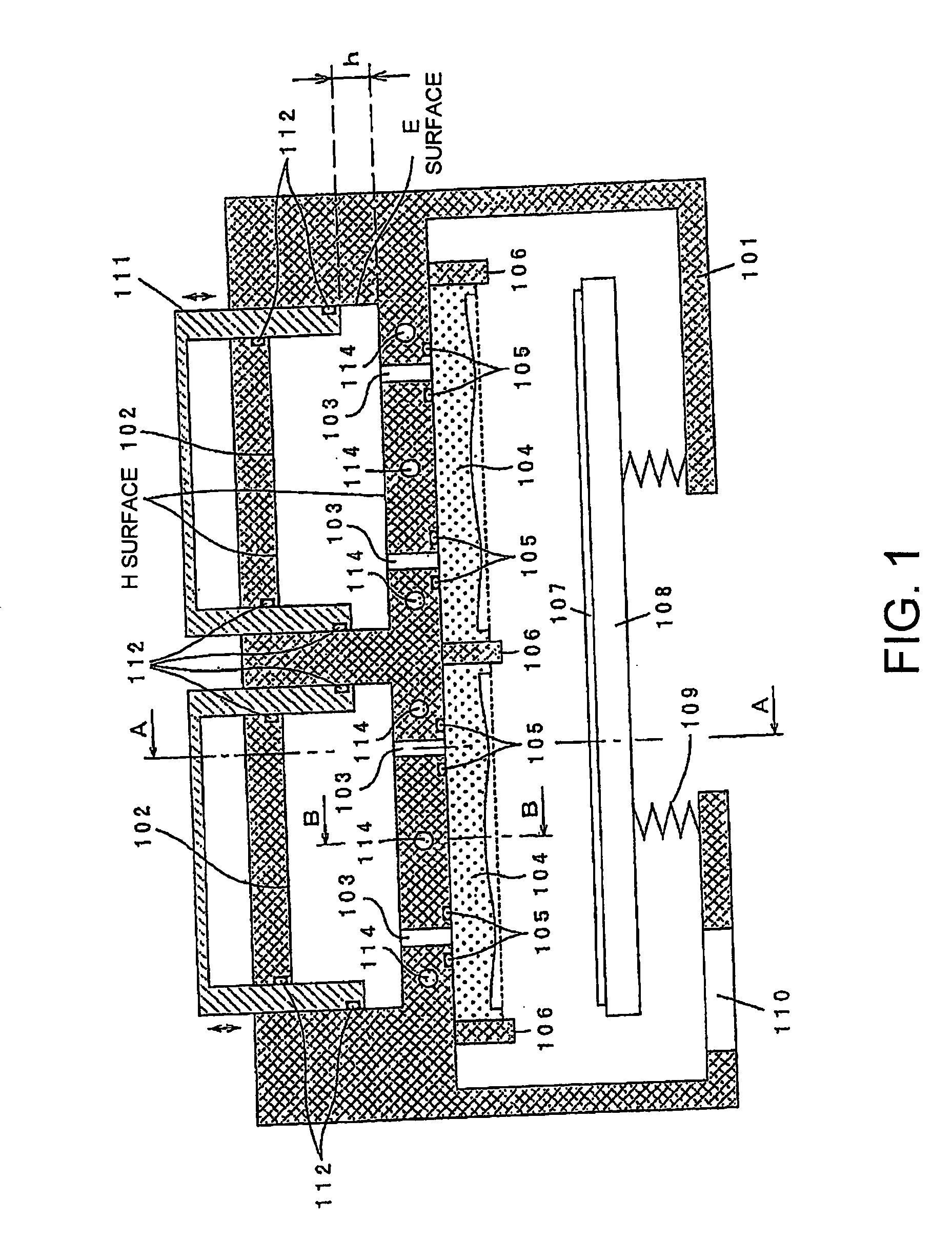
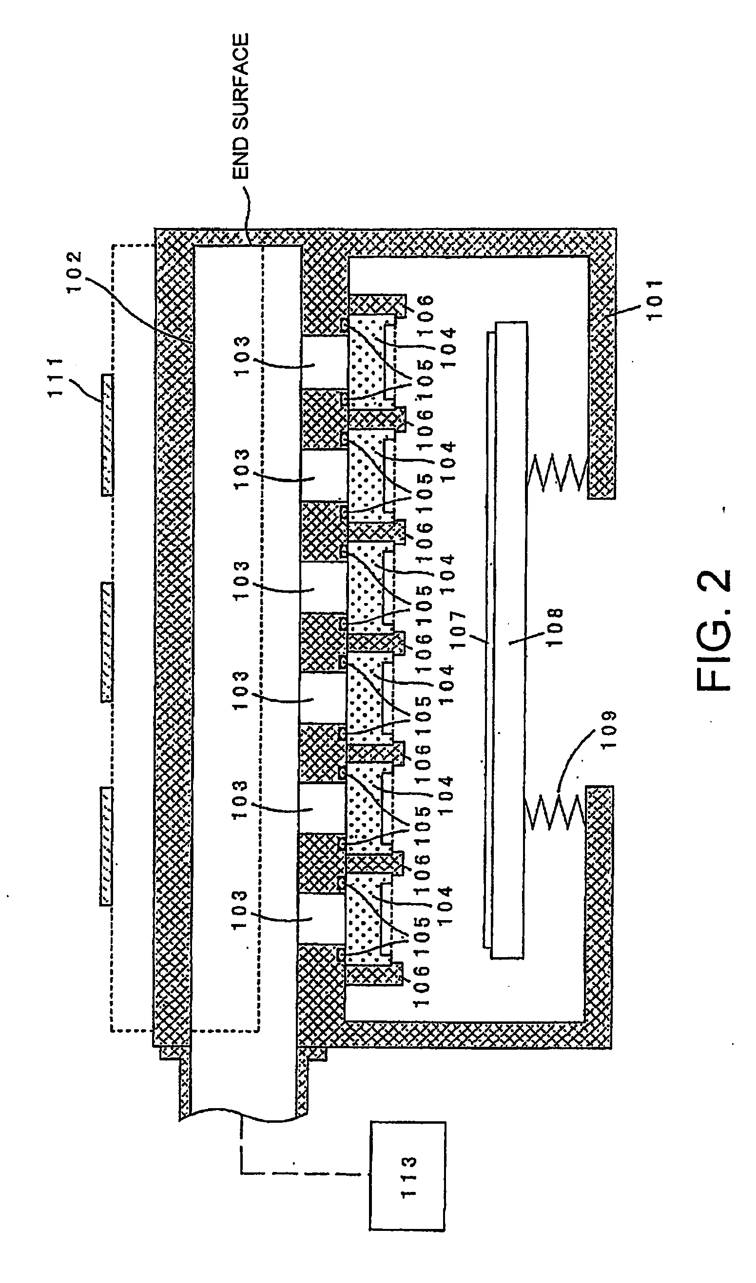
[0036]FIG. 1 is a sectional view showing the first embodiment among the plasma processing apparatuses of this invention. FIG. 2 is a sectional view taken along A-A in FIG. 1 and FIG. 3 is a sectional view taken along B-B in FIG. 1.

[0037]A vacuum container 101 is made of, for example, aluminum and is in a state of being grounded. A substrate 107 and a stage 108 for the substrate 107 are provided in the vacuum container 101. The substrate 107 is, for example, a glass substrate. A bellows 109 is provided between the stage 108 and the vacuum container 101, so that the stage 108 can be moved up and down by a non-illustrated elevator mechanism while maintaining airtightness. In the lower part of the vacuum container 101, there are provided exhaust ports 110 for exhausting gas in the vacuum container 101 by the use of a vacuum pump or the like provided outside the vacuum container 101.

[0038]Two rectangular waveguides 102 are disposed in parallel to each other, i.e. with their H surfaces (w...

embodiment 2

[0075]FIG. 9 is a sectional view showing the second embodiment among the plasma processing apparatuses of this invention. Herein, only what is different from the first embodiment will be described.

[0076]On the surface of each waveguide 102 on the side of a stage 108, rectangular parallelepiped dielectric plates 104 are disposed in one-to-one correspondence with slots 103. It may be configured that each dielectric plate 104 may be arranged so as to lie over the plurality of waveguides 102.

[0077]An in-waveguide dielectric 201 is provided in each waveguide 102. The in-waveguide dielectric 201 is made of a fluororesin having a relative permittivity of 2.1, but may be made of quartz, mullite, alumina, sapphire, yttria, aluminum nitride, silicon nitride, or the like. If the dielectric is inserted in the waveguide as described above, the size of a waveguide section and the guide wavelength λg are reduced. Given that the relative permittivity of an in-waveguide dielectric is “∈r”, the size ...

embodiment 3

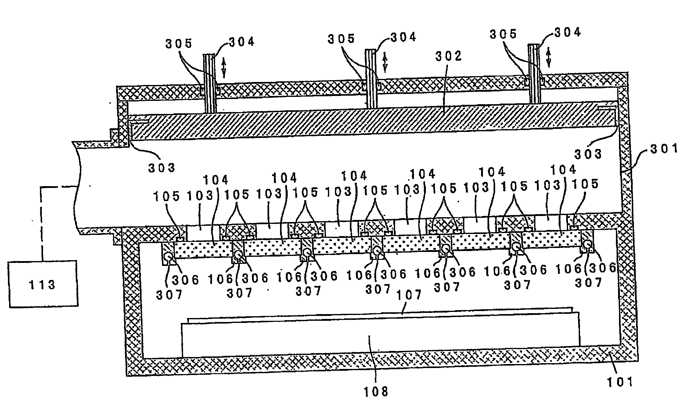
[0084]FIG. 11 is a sectional view showing the third embodiment among the plasma processing apparatuses of this invention. FIG. 12 is a sectional view taken along A-A in FIG. 11. Herein, only what is different from the first embodiment will be described.

[0085]A single rectangular waveguide 301 is disposed with its E surfaces (narrow wall surfaces of the rectangular waveguide) being parallel to a substrate 107. The waveguide 301 has one end forming a short-circuit surface and the other end to which a microwave supply system 113 is connected. In this embodiment, since an elongated plasma can be produced, it is suitable for the case where plasma processing is carried out for an elongated member or the case where plasma processing is carried out while moving a large-area substrate in a direction perpendicular to the axis of the waveguide.

[0086]A plurality of slots 103 are formed at regular intervals in a surface, on the side of a stage 108, of the waveguide 301. On the surface of the wav...


PUM

PropertyMeasurementUnit
Lengthaaaaaaaaaa
Lengthaaaaaaaaaa
Lengthaaaaaaaaaa

Abstract

Provided is a plasma processing apparatus which can perform uniform processing even when a substrate to be processed has a large area. The plasma processing apparatus propagates microwaves introduced into wave guide tubes to dielectric plates through slots, and performs plasma processing to the surface of the substrate by converting a gas supplied into a vacuum container into the plasma state. In the plasma processing apparatus, a plurality of waveguide tubes are arranged in parallel, a plurality of dielectric plates are arranged for each waveguide tube, and partitioning members formed of a conductor and grounded are arranged between the adjacent dielectric plates. The in-tube wavelength of the waveguide tube is adjusted to be an optimum value by vertically moving a plunger. Furthermore, unintended plasma generation is eliminated in a space between the dielectric plate and the adjacent member, and stable plasma can be efficiently generated. As a result, high-speed and uniform processings, such as etching, film-forming, cleaning, ashing, can be performed.

Description

TECHNICAL FIELD[0001]This invention relates to a plasma processing apparatus and, in particular, relates to a plasma processing apparatus capable of uniformly processing a large-area substrate.BACKGROUND ART[0002]A plasma processing method is a processing method that produces highly active ions and radicals (free radicals) by converting a specific gas into a plasma, thereby carrying out processing such as etching, film-forming, cleaning, or ashing on the surface of a processing substrate. A plasma processing apparatus is an apparatus for use in performing the plasma processing method. Energy for converting a gas into a plasma is often given by an electromagnetic wave. In the manufacturing process of semiconductors, solar cells, flat panel displays, or the like, use is made of a parallel-plate plasma processing apparatus using a high frequency of several MHz to several tens of MHz as an energy medium for converting a gas into a plasma, or an inductively coupled plasma processing appa...

Claims


Application Information

Patent Timeline
IPC IPC(8): B44C1/22C23F1/08B01J19/08C23C16/54
CPCH05H1/46H01J37/32192C23C16/511H05H1/24H01L21/0262
Inventor OHMIHIRAYAMA, MASAKI
Owner TOHOKU UNIV
Learn More