Rotary Valve for Industrial Fluid Flow Control

Inactive Publication Date: 2009-03-12
MITTON VALVE TECH
View PDF10 Cites 26 Cited by
  • Summary
  • Abstract
  • Description
  • Claims
  • Application Information

AI Technical Summary

Benefits of technology

[0029]These valves may be used in a wide variety of applications, with a wide variety of benefits, which may include, but are not limited to one or more of, reduced pressure loss in the valve, vibration reduction, noise reduction, reduced wear and friction, ease of cleaning, reduced manufacturing costs, reduced number of parts, less maintenance, faster and more accurate valve timing, ease of replacement of parts and calibration of systems by changing only the valve shaft.
[0030]The present invention also encompasses the replaceable nature of the shafts, referred to as a modular cylindrical rotary valve system. In general, this system comprises a valve body and a replaceable first cylindrical valve shaft positioned coaxially within the first cylindrical bore. The outer surface of the first cylindrical valve shaft defines a first conduit profile. A conduit profile denotes the cross sectional area of the conduit relative to the direction of flow for a given rotational position of the shaft. The first cylindrical valve shaft is replaceable with a second cylindrical valve shaft defining a distinguishable second conduit profile when positioned within the valve body. When

Problems solved by technology

In either case, flow is controlled by rotating the valve gate through a sufficient number of degrees (typically 90°) so that the passage no longer provides fluid communication between the input and output ports of the valve housing.
Consequently, mounting the multiple valve gates results in a less efficient seal compared to a single ball valve.
Spherical valves, or indeed any valves, mounted on a shaft have known heat transfer

Method used


Image

  • Rotary Valve for Industrial Fluid Flow Control
  • Rotary Valve for Industrial Fluid Flow Control
  • Rotary Valve for Industrial Fluid Flow Control

Examples


Example

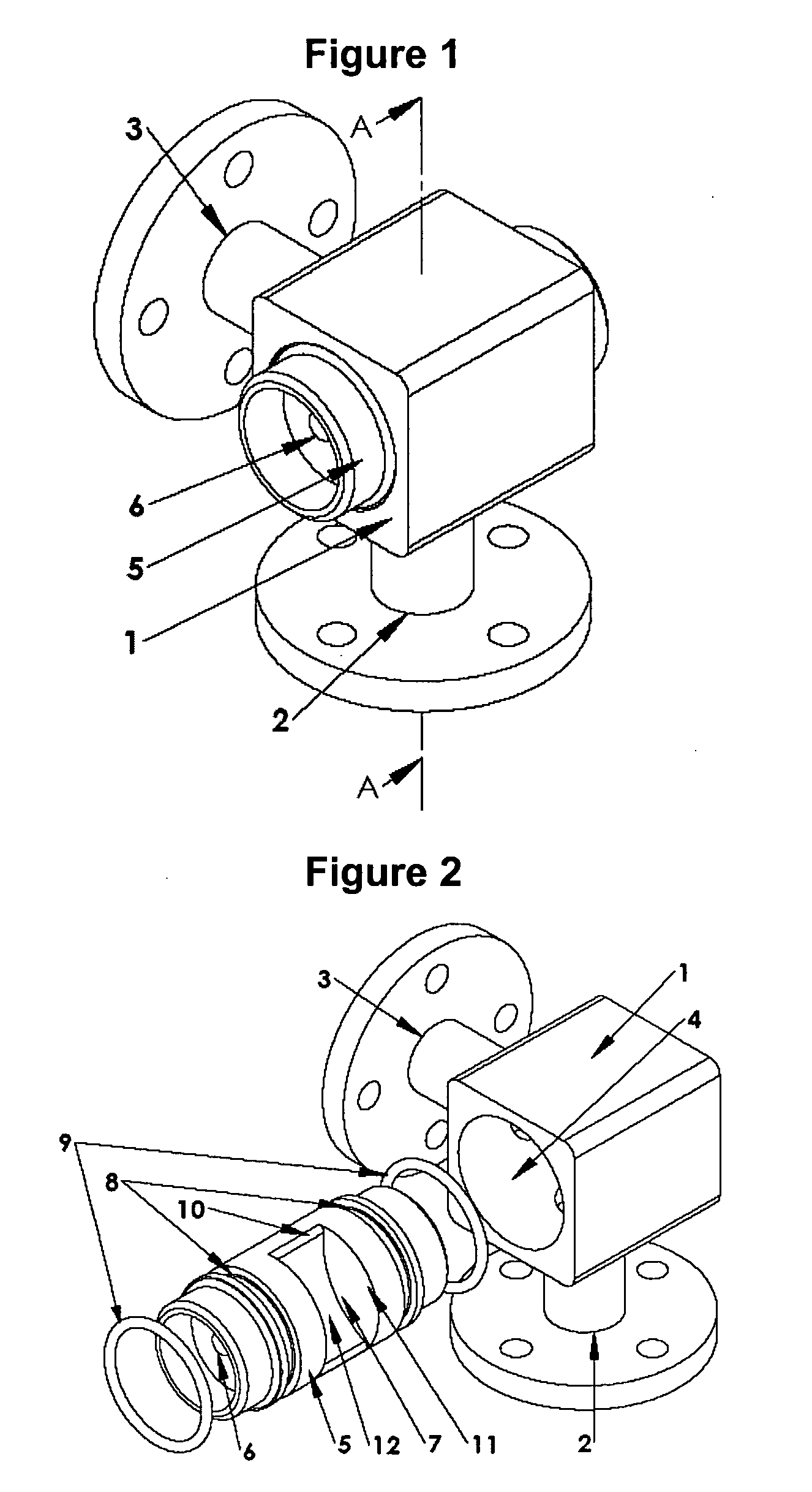
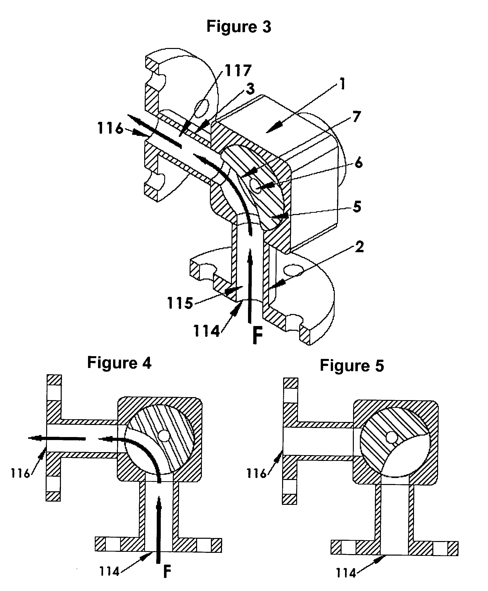
[0086]FIG. 1 and FIGS. 2 through 17 depict a first embodiment of the invention, namely a one input and one output configurable valve in use as a on / off (stop) valve.

[0087]FIG. 1 shows two port valve body 1 with inserted valve shaft 5. The valve body 1 has interchangeable input pipe 2 and output pipe 3, shown in this embodiment to be at 90 degrees from each other. The valve body houses a standard size valve shaft 5, with optional temperature control bore 6. To maintain the generality of the invention, the drive means for the valve is not shown, although a variety of accurate and robust means to control the rotation of the shaft will be known to those of skill in the art, who will be in a position to determine an appropriate drive means compatible with the tolerances of the proposed use. Also not shown is the specific element used to connect the temperature control core 6 with the temperature control fluid. There are well known means to attach a rotating pipe in fluid communication wi...

Example

Embodiment 2

Pulse Valve

[0099]FIG. 1 and FIGS. 18 through 27 disclose embodiments of the present invention configured to create a flow pulse in the fluid being controlled at the output of the valve body. The various embodiments demonstrate the design parameters that are available for use in the present invention. This embodiment includes a valve body 1 with input pipe 2, output pipe 3 as disclosed in FIG. 1. The exploded view in FIG. 18 shows the valve body 1 further provided with the hollow 4 in the valve body 1 sized to accept a standard radius cylindrical valve shaft 50. The cylindrical valve shaft may be equipped with a temperature control core 51. In this example, symmetrical crescent shaped conduits 52 are spaced evenly about the shaft. If required by the choice of material, seal channels 53 are cut around the valve shaft 50 on either side of the conduits 52 into which seals 54 are inserted. A self lubricating coating on the valve shaft 50 may also be provided.

[0100]The valve s...

Example

Embodiment 3

Wave Valve.

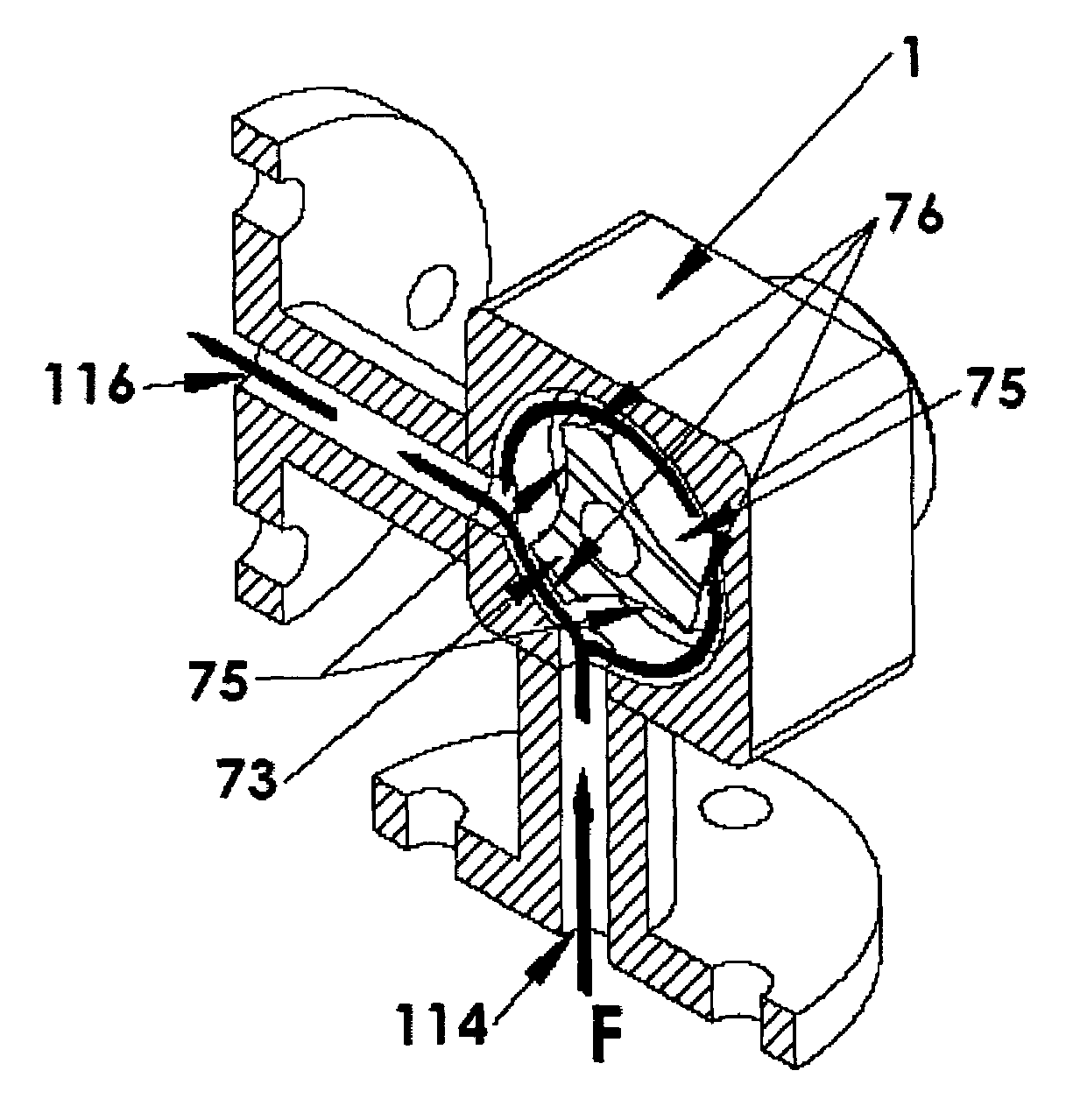
[0105]Yet another variation of the pulse valve is a “wave-valve” as shown in FIGS. 30, 31, 32A and 32B. In certain embodiments, it is desirable to create a known gap size in the clearance between the valve body (housing) and the valve shaft, in addition to the conduits previously described, so that fluid flow can be accurately controlled without entirely turning off fluid flow. This creates a “wave” or “offset pulse” in the fluid which is useful in certain applications. The prior art teaches away from intentionally inserting gaps into the space between the valve body and the valve shaft, to improve the seal and eliminate “leakage”. In contrast, certain wave valve embodiments of the invention allow a user to predetermine, and thereby quantify, the “leak” to suit a design purpose.

[0106]The overall wave valve configuration is similar to the pulse valve. FIG. 30 and FIG. 31 show two views of a three conduit wave type valve shaft 73, with optional temperature contr...


PUM

PropertyMeasurementUnit
Temperatureaaaaaaaaaa
Pressureaaaaaaaaaa
Flow rateaaaaaaaaaa

Abstract

A cylindrical rotary valve to control or affect fluid flow in processes where the fluid temperature must be maintained within a target range, the fluid pressure is varied and/or the amount of fluid flow is controlled comprising one or more of the following elements alone or in combination: (i) the use of a temperature control core in the valve shaft, (ii) the contoured or tapered shapes or the conduits (iii) the use of the valve to create predictable pulses or waves in the fluid being controlled, (iv) a modular system of valves where the valve body is fixed and the valve shaft is replaceable with a second valve shaft of different conduit shape, (v) a rotary valve with multiple inputs or multiple outputs for either mixing or diverting of input fluids, and (vi) the use of the valve in abrasive particulate blasting and in particular dry ice blasting.

Description

FIELD OF THE INVENTION[0001]The present invention relates to a rotary valve with a cylindrical valve shaft and valve housing to control or affect fluid flow, also to control or affect fluid flow in processes where the fluid temperature must be maintained within a target range, the fluid pressure is varied and / or the amount of fluid flow is controlled.BACKGROUND OF THE INVENTION[0002]Valves are a well known part of industrial, research and residential fluid flow processes, where the valve either inhibits (e.g, in the case of a stop valve), regulates (e.g., in the case of a check valve) or affects (e.g. in creating or dampening pressure pulses in the fluid) the flow of fluid in a system. Between the input and output directions of the valve, the shape and seal of the valve gate determines many of the functions and properties of the valve.[0003]Prior industrial applications requiring fluid flow control have typically depended on either poppet, spool, butterfly or ball valves to either c...

Claims


Application Information

Patent Timeline
IPC IPC(8): F16K5/10F16K5/04B24C3/02F16K5/22
CPCB24C1/003F16K5/0407F16K49/007F16K5/225F16K11/0853F16K5/0414Y10T137/6058Y10T137/4358B01F25/1051B01F31/65
Inventor MITTON, MICHAEL JONMCLEAN, MARSHALL JAMES DOUGLASGROSU, VIOREL
Owner MITTON VALVE TECH
Why Eureka
Try Eureka