Reduced-friction coatings

a coating and friction technology, applied in the field of coatings, can solve the problems of loss of phase structure control, destabilization of bulk structure, loss of ag to the surface, etc., and achieve the effects of reducing friction, reducing wear and temperature, and reducing energy

Inactive Publication Date: 2009-03-19
NORTHWESTERN UNIV
View PDF7 Cites 38 Cited by
  • Summary
  • Abstract
  • Description
  • Claims
  • Application Information

AI Technical Summary

Benefits of technology

[0011]A coating or coated substrate in accordance with the invention is advantageous to save energy through reduced friction and mitigates against excessive wear and temperature increases of a workpiece or member in contact with the coating. Practice of the invention in the machining of metallic workpieces also can help to reduce a major source of industrial waste in the form of contaminated cooling liquids since the metal powder, flakes, curls, etc. resulting from machining can be collected dry and recycled easily and also can help to reduce hazardous mists that can cause respiratory problems in the work place.
[0012]A coating in accordance with the invention can be deposited by standard (economical) tool coating methods and replace expensive, and highly specialized coatings such as polycrystalline diamond that are currently used in some machining applications to achieve necessary durability and performance where liquids are not used to cool or lubricate. The coating can have a primary function as in cutting to maintain low friction, or the coating can serve as a fail-safe coating where, under extreme conditions when lubrication is momentarily absent from a contact surface, seizure and failure can be prevented by the coating until lubricant can be supplied in adequate amounts.

Problems solved by technology

To this end, others have explored incorporation of elements that readily oxidize to form lubricious oxides (e.g. V), but which unfortunately diffuse readily to the surface in the host material and result in destabilized structures in the bulk.
Still others are looking into the incorporation of low melting metals such as silver, but this too diffuses rapidly to the surface (and to internal surfaces / grain boundaries) and so control of the phase structure and the flux of Ag to the surface is lost.

Method used


Image

  • Reduced-friction coatings
  • Reduced-friction coatings
  • Reduced-friction coatings

Examples


examples

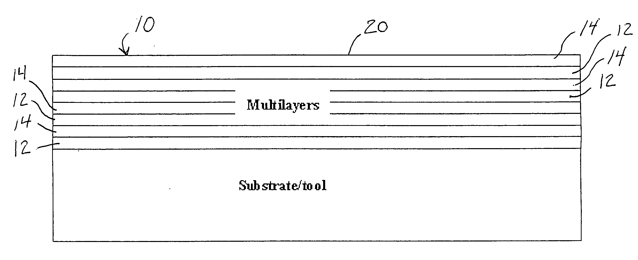
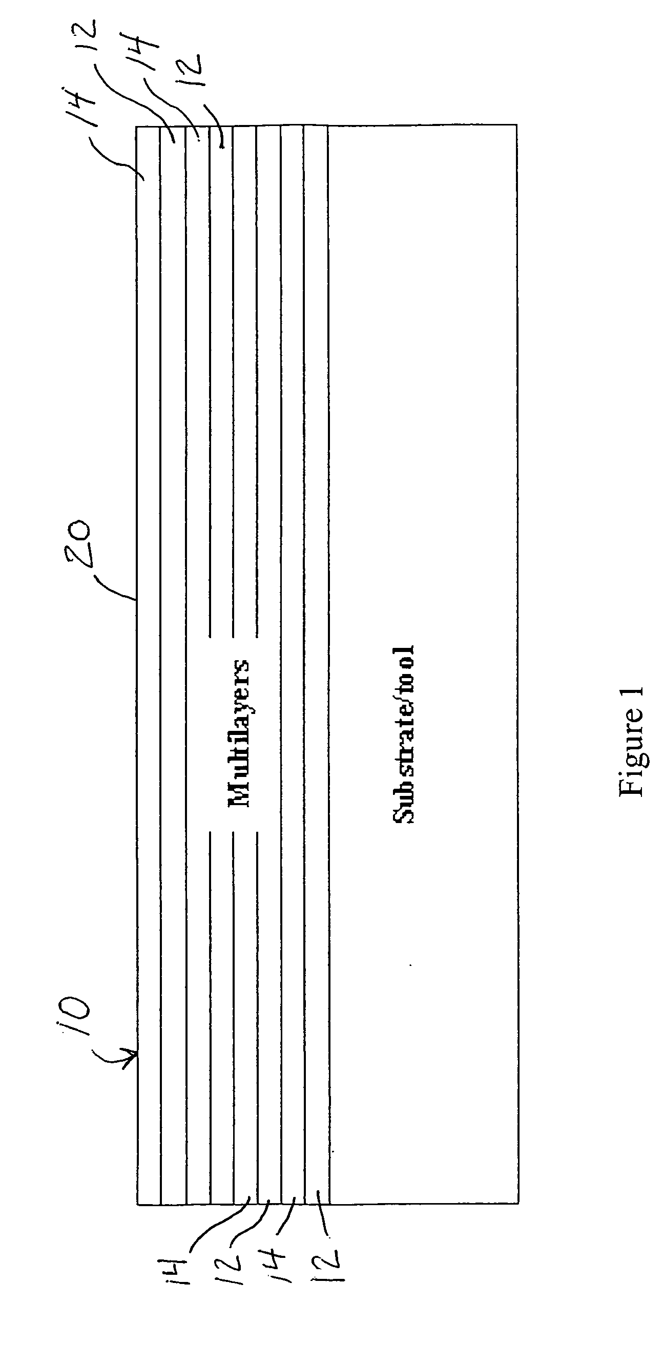
[0030]Samples were prepared by sputter deposition in a closed-field dual cathode unbalanced magnetron system. The cryo pumped system has a base pressure of 4×10⁻⁷ Torr and includes a high vacuum load lock chamber. There are two vertically mounted 12.8×40.6 cm planar magnetron cathodes facing each other on opposite sides of the substrate holder and 10 cm from the substrates. The hexagonal substrate holder is just large enough to eliminate the cross contamination from the other cathode. The substrate holder can be rotated at 5-15.2 rpm to produce nano-layered materials with controlled layer thickness. All coatings were 1 to 1.5 μm thick in total thickness. The substrates were single crystal Si (001), glass sides, and polished M50 tool steel discs. Sapphire substrates were used in cases where high temperature anneals were to be carried out. Prior to deposition the samples were cleaned in an ultrasonic bath of methanol. All reactive sputter depositions were carried out under a total pre...


PUM

PropertyMeasurementUnit
thicknessaaaaaaaaaa
temperaturesaaaaaaaaaa
pressureaaaaaaaaaa

Abstract

A coating is provided having a first metal or non-metal nitride layer and a second metal or non-metal nitride layer wherein the first and second nitride layers are sufficiently resistant to interdiffusion to maintain respective individual layer structure and strength at an elevated operating temperature when a coating contact surface is in sliding contact with another material and wherein one of the first layer or second layer includes a component that is oxidizable at the contact surface to form a friction-reducing lubricous oxide material at the contact surface.

Description

[0001]This application claims benefits and priority of provisional application Ser. No. 60 / 994,041 filed Sep. 17, 2007, the disclosure of which is incorporated herein by reference.CONTRACTUAL ORIGIN OF THE INVENTION[0002]This invention was made with government support under contract DMI-0423419 awarded by the National Science Foundation. The U.S. government has certain rights in the invention.FIELD OF THE INVENTION[0003]The present invention relates to coatings and, more particularly, to coatings that undergo in-situ oxidation of a coating component to reduce friction at a contact surface as well as to coated tools and other substrates.BACKGROUND OF THE INVENTION[0004]Hard coatings for cutting tools have been in use now for thirty years and have evolved from the initial, simple nitride and oxide coatings (such as TiN and Al2O3) applied by CVD and PVD in the 1970s, to more complex, high-performance alloy nitrides (such as TAN) employed today.[0005]More recently, the interest in green...

Claims


Application Information

Patent Timeline
Patent Type & Authority Applications(United States)
IPC IPC(8): B23B27/14C10M125/00C10M125/20C10M125/26
CPCB23B27/14Y10T407/27B23B2228/10B23B2228/105B23B2228/52C10M103/06C10M2201/0613C10M2201/0873C10N2210/06C10N2230/06C10N2250/121C23C30/005C23C28/044C23C28/42B23B2222/64C10N2010/12C10N2030/06C10N2050/02
Inventor GRAHAM, MICHAEL E.KOSHY, ROBIN A.MARKS, LAURENCE D.
Owner NORTHWESTERN UNIV
Why Eureka
Try Eureka