Electric storage device

a technology of electric storage device and secondary battery, which is applied in the direction of cell components, sustainable manufacturing/processing, secondary cell details, etc., can solve the problems of reduced energy and difficulty in assembly, so as to ensure the durability of electric storage device and enhance energy density and output density of electric storage device.

Active Publication Date: 2009-03-19
SUBARU CORP
View PDF2 Cites 16 Cited by
  • Summary
  • Abstract
  • Description
  • Claims
  • Application Information

AI Technical Summary

Benefits of technology

[0020]According to the present invention, since the first negative-electrode mixture layer and the second negative-electrode mixture layer, which are of different types, are combined and used, the energy density and the output density of the electric storage device can be enhanced. Further, since the through-hole is formed on the current collector arranged between the first negative-electrode mixture layer and the second negative-electrode mixture layer, ions can move between the first negative-electrode mixture layer and the second negative-electrode mixture layer. Consequently, even if the first negative-electrode mixture layer and the second negative-electrode mixture layer, which are of different types, are combined, the variation in the potential between the first negative-electrode mixture layer and the second negative-electrode mixture layer can be canceled, whereby the durability of the electric storage device can be ensured.

Problems solved by technology

However, the lithium ion secondary battery has a high energy density, but low output density.
However, in the former method, the electrode mixture material is coated to be thin, which entails a reduction in the energy density of the electric storage device, or which makes the assembly difficult to thereby increase cost of the electric storage device.
In the latter method, the battery and the capacitor are combined, which entails increased cost of the electric storage device due to a complicated control circuit.
However, in the electric storage device disclosed in JP-A-2001-351688, it is difficult to cancel the deviation in the potential between the electrodes that are connected to each other.
The occurrence of the over discharge or overcharge described above causes the deterioration in the durability of the electric storage device.
In the electric storage devices disclosed in JP-A-2000-36325, JP-A-2005-203131, and International Publication WO2002 / 41420, it is difficult to ensure the output density by sufficiently reducing the internal resistance, since the device has a structure in which the active carbon and the lithium cobalt oxide are mixed or a structure in which the active carbon and the lithium cobalt oxide are laminated.
Therefore, the effect caused by the deteriorated lithium cobalt oxide also affects the active carbon, which deteriorates the durability of the electric storage device.

Method used


Image

  • Electric storage device
  • Electric storage device
  • Electric storage device

Examples


example 1

[Fabrication of Negative Electrode 1]

[0066]A furfuryl alcohol, which was a raw material of a furan resin, was retained at 60° C. for 24 hours so as to cure the furfuryl alcohol, to thereby obtain a black resin. The obtained black resin was put into a stationary electric furnace, and heat-treated for 3 hours under a nitrogen atmosphere till the temperature reached 1200° C. The black resin was retained at 1200° C. for 2 hours. The sample taken out after the cooling was pulverized by means of a ball mill to obtain a hard carbon powder (D50=5.0 μm, hydrogen atom / carbon atom=0.008) as a sample 1.

[0067]Then, 86 parts by weight of the sample 1, 6 parts by weight of acetylene black powder, 5 parts by weight of acrylic resin binder, 3 parts by weight of carboxylmethyl cellulose, and 200 parts by weight of water were fully mixed to obtain a slurry 1 for a negative electrode. The slurry 1 for a negative electrode was uniformly applied onto both surfaces of an expanded metal made of copper in a...

example 2

Examination for Example 2

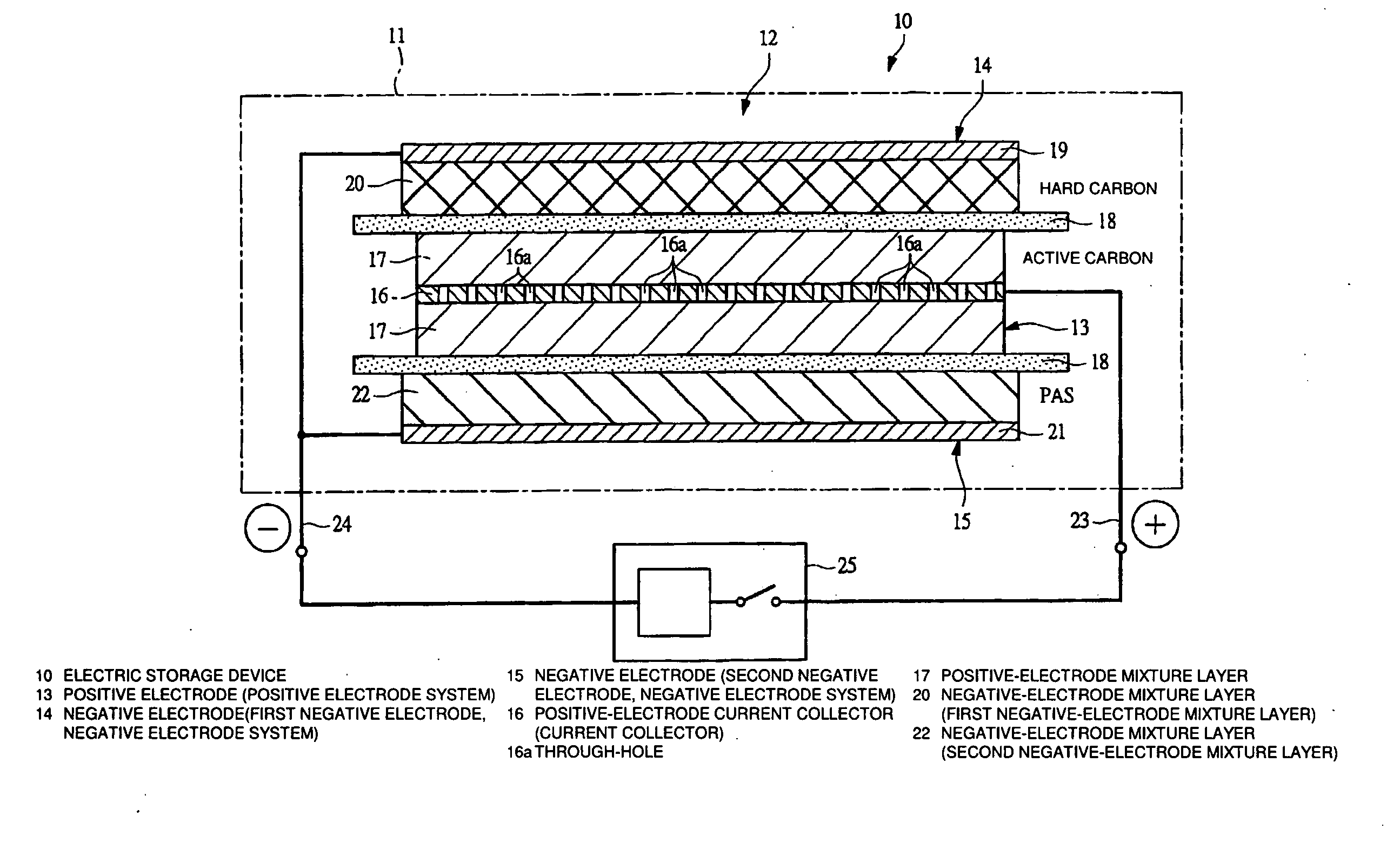
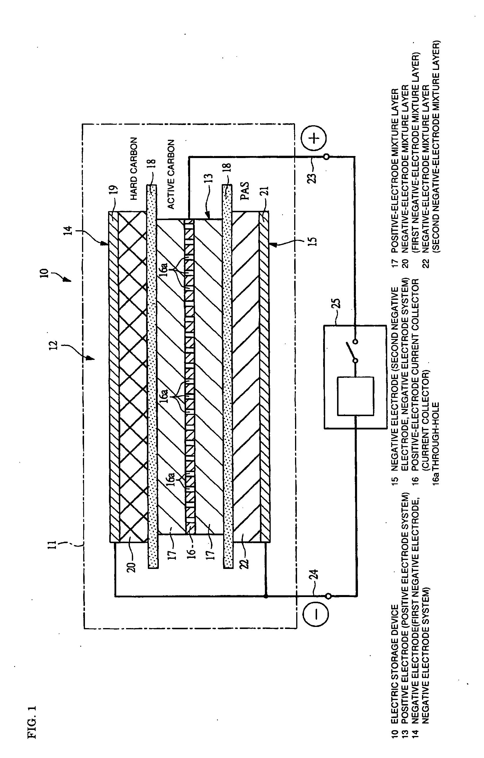
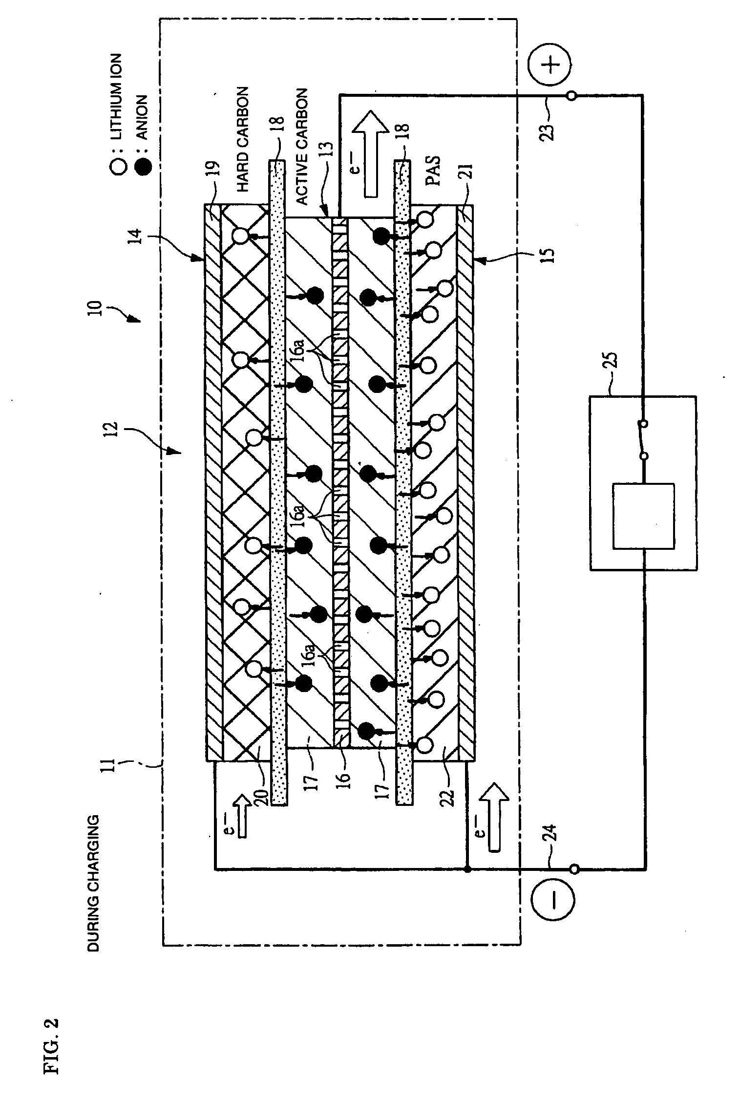
[0093]Like the cell 1 according to the Example 1, it was confirmed that the cell 4 according to the Example 2 had a high energy density and a high capacity retention ratio, since it had the negative electrode 3 including the negative-electrode mixture layer containing the hard carbon with a high capacity at one surface and the negative-electrode mixture layer containing the PAS with a low resistance on the other surface. When the cell 4 that was subject to the charge / discharge test performed 1000 times under a low temperature of −20° C. was disassembled, the deposition of the metal lithium was not recognized on the negative electrode 3 containing the hard carbon, which had a high resistance. Like the cell 1 according to the Example 1, when the cell 4 according to the Example 2 is charged, many lithium ions move to the negative-electrode mixture layer containing the PAS having a low resistance, and then, these lithium ions slowly move to the negative-electrod...

example 3

[Fabrication of Positive Electrode 2]

[0094]92 parts by weight of commercially available LiCoO2 powder, 4.5 parts by weight of graphite powder, and 3.5 parts by weight of polyvinylidene fluoride (PVdF) powder were mixed, and then, N-methyl pyrrolidone was added thereto. The resultant was thoroughly stirred and defoamed, where by a slurry 2 for a positive electrode was obtained. The slurry 2 for a positive electrode was uniformly applied over both surfaces of the positive-electrode current collector by means of a roll coater, and dried and pressed to produce a positive electrode 2 having a thickness of 169 μm.

[Fabrication of Electrode Laminate Unit 5]

[0095]The negative electrode 1 was cut out into six pieces, each having an area of 6.0 cm×7.5 cm (excluding the terminal welding parts), the negative electrode 2 was cut out into six pieces, each having an area of 6.0 cm×7.5 cm (excluding the terminal welding parts), and the positive electrode 2 was cut out into eleven pieces, each having...


PUM

PropertyMeasurementUnit
currentaaaaaaaaaa
specific surface areaaaaaaaaaaa
pore diameteraaaaaaaaaa

Abstract

A positive electrode 13 includes a positive-electrode current collector 16 provided with a large number of through-holes 16a and a positive-electrode mixture layer 17 applied thereon. Negative electrodes 14 and 15 are arranged so as to sandwich the positive electrode 13. A negative-electrode mixture layer 20 of the negative electrode 14 contains a hard carbon having a high capacity characteristic, while a negative-electrode mixture layer 22 of the negative electrode 15 contains a PAS having a high output characteristic. Since the negative electrodes 14 and 15, each having a different charge/discharge characteristic, are provided, an energy density and an output density of the electric storage device 10 can be enhanced. Ions can move between the negative-electrode mixture layers 20 and 22 via the through-holes 16a, whereby a variation in the potential of the negative electrodes 14 and 15 can be canceled, even in case where the negative electrodes 14 and 15 each having a different charge/discharge characteristic are combined. Therefore, the durability of the electric storage device 10 can be secured.

Description

CROSS-REFERENCE TO RELATED APPLICATIONS[0001]The disclosure of Japanese Patent Application No. 2007-240986 filed on Sep. 18, 2007 including the specification, drawing and abstract is incorporated herein by reference in its entirety.BACKGROUND OF THE INVENTION[0002]1. Field of the Invention[0003]The present invention relates to a technology that is well adaptable to an electric storage device including plural negative electrodes.[0004]2. Description of the Related Arts[0005]High energy density and high output density are required for an electric storage device that is mounted to an electric vehicle, a hybrid vehicle, or the like. Therefore, a lithium ion secondary battery, an electric double layer capacitor, etc. have been nominated as a candidate for the electric storage device. However, the lithium ion secondary battery has a high energy density, but low output density. The electric double layer capacitor has a high output density, but low energy density.[0006]In view of this, ther...

Claims


Application Information

Patent Timeline
Patent Type & Authority Applications(United States)
IPC IPC(8): H01M10/02H01M4/58H01M4/13H01M4/133H01M4/137H01M4/60H01M4/70H01M10/052H01M10/0525H01M10/0585H01M10/0587
CPCH01M4/13H01M4/137H01M4/366H01M4/587H01M4/661H01M4/70Y02T10/7011H01M4/80H01M10/0413H01M10/0525H01M10/058Y02E60/122H01M4/74Y02E60/10Y02P70/50H01G11/72Y02T10/70
Inventor ANDO, NOBUOKOJIMA, KENJIHATOU, YUKINORI
Owner SUBARU CORP
Why Eureka
Try Eureka