[0008]It is a further object of the present invention to provide a method and apparatus for extending the duration of a laser pulse, which is simply and rapidly adapted to various different laser systems and / or different applications.
[0009]It is another object of the present invention to provide a method and apparatus for generating a laser pulse of various different lengths or durations from a single incident laser pulse of given length, which is simple and rapidly adapted to various different laser systems and / or different applications.
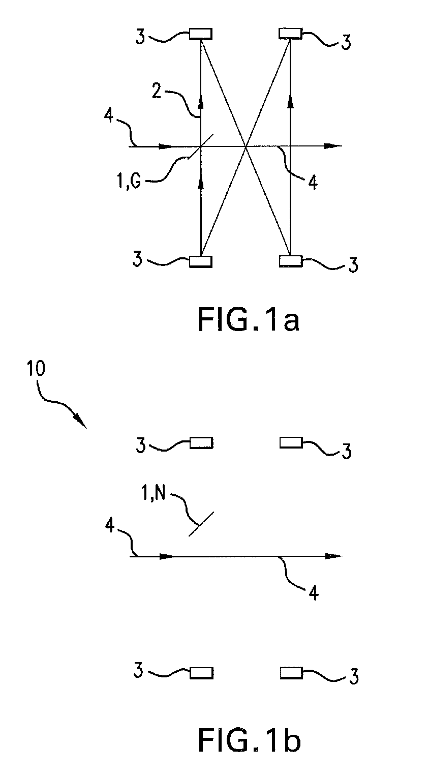
[0012]The delaying travel path section or device may be advantageously switched on or off in this way, when the
beam splitter is moved into the disengaged or the engaged position. This adjustment for example can occur by a local displacement of the beam splitter. Similarly an adjustment of the engaged position or the disengaged position can occur by displacing or switching optical elements, which either conduct the laser beam through the beam splitter or not according to their position. The delaying travel path section according to the invention thus facilitates an
adaptation in a simple way, for example to the laser that is used, the measurement to be performed, or the
exposure. It is especially advantageous that the laser beam properties of the laser that is employed, such as the beam cross-section, the wave front curvature, and the
divergence, remain the same in the elongated pulses produced by the method and apparatus according to the invention. The beam properties will remain particularly the same, when a correctly aligned and telecentric 1:1-imaging delaying travel path section or device is used. As reflectors, at least four concave mirrors are used in preferred embodiments of the method and apparatus according to the invention. These concave mirrors are arranged like an at least double 1:1
telescope.
[0017]The
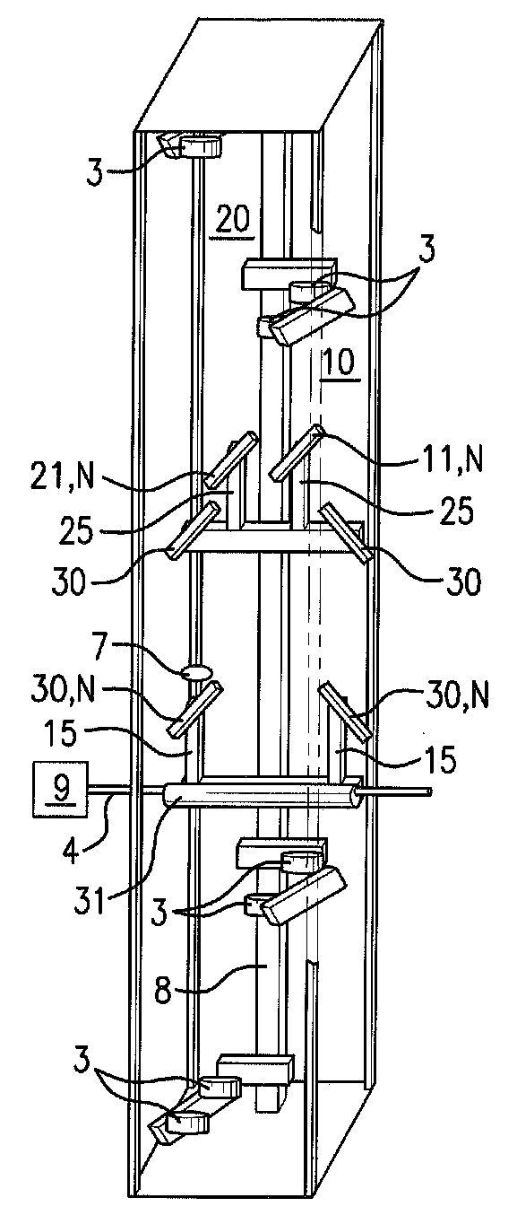
subject matter of the invention also includes an apparatus for producing extended duration or lengthened laser pulses with a plurality of delaying travel path sections. Preferably several of the delaying travel path sections are constructed according to the present invention. An apparatus, With which a laser pulse can be extended or lengthened in its duration, is called a
pulse stretcher. This is possible without further effort simply by turning on or off at least one delaying travel path section according to the invention. Plural delaying travel path sections are each switchable between an active and an inactive state in preferred embodiments of the invention. In this way testing of materials by means of laser pulses is made easier and simpler. The materials can be exposed to different laser pulses of different duration and
peak intensity, without changing the beam profile, for example regarding
beam cross section, wave front curvature, or
divergence. It is especially advantageous that an economical
single stage laser with comparatively poor beam properties can be used.
[0018]The apparatus according to the invention preferably has a lens or a lens
system for adjustment of the beam properties of a laser. The laser beam first passes through the lens or lens
system prior to passing through the delaying travel path section. Particularly preferably
divergence, especially of the wave front curvature, of the laser beam is partially compensated by a
cylindrical lens. The comparatively large divergence of the beam of a low-cost
single stage laser due to the comparatively large wave front curvature, which can lead to different (poorer positions) positions of the beam middle, and thus which can lead to unequal loads and destruction of the optical components, may be partially compensated in an advantageous manner, so that the beam middle is arranged approximately centrally between the reflecting mirrors of the delaying travel path section. The laser beam that is used for example can have a rectangular cross-section so that the
cylindrical lens can only correct divergence of the long dimension of the laser cross-section. Advantageously a uniformly low beam load on the optical elements, for example the mirrors, is attained in the delaying travel path section and thus allows the use of different laser sources in the apparatus according to the invention, because of the use of the lens and / or the lens
system adapted to the laser beam properties prior to the delaying travel path section.
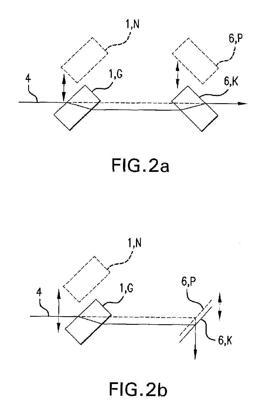
[0020]Preferably a correcting element, which acts to correct the beam displacement, is associated with one or more delaying travel path sections. Each delaying travel path section can be associated with a correcting element. Likewise the apparatus preferably has one or more correcting elements, which are independent of the delaying travel path sections. For example, a beam displacement can be compensated with two delaying travel path sections connected in series and even by their
beam splitters, so that additional correcting elements are not required. This latter saving is advantageous since a reduced number of optical elements leads to reduced losses.

