Process for selective area deposition of inorganic materials

a technology of inorganic materials and selective area deposition, which is applied in the direction of vacuum evaporation coating, chemical vapor deposition coating, coating, etc., can solve the problems of limiting device processing to below 200° c, requiring relatively difficult or complicated processes, and amorphous silicon deposition

Active Publication Date: 2009-03-26
EASTMAN KODAK CO
View PDF9 Cites 106 Cited by
  • Summary
  • Abstract
  • Description
  • Claims
  • Application Information

AI Technical Summary

Benefits of technology

[0044]It is an advantage of the present invention that selective deposition of metal oxides and other materials are used in a process combined with a spatially dependent ALD system.
[0045]It is an advantage of the present invention that it is adaptable for deposition on a web or other moving substrate, including deposition onto a large area substrate.
[0046]It is a further advantage of the present invention that it allows operation, in preferred embodiments, under atmospheric pressure conditions.
[0047]It i...

Problems solved by technology
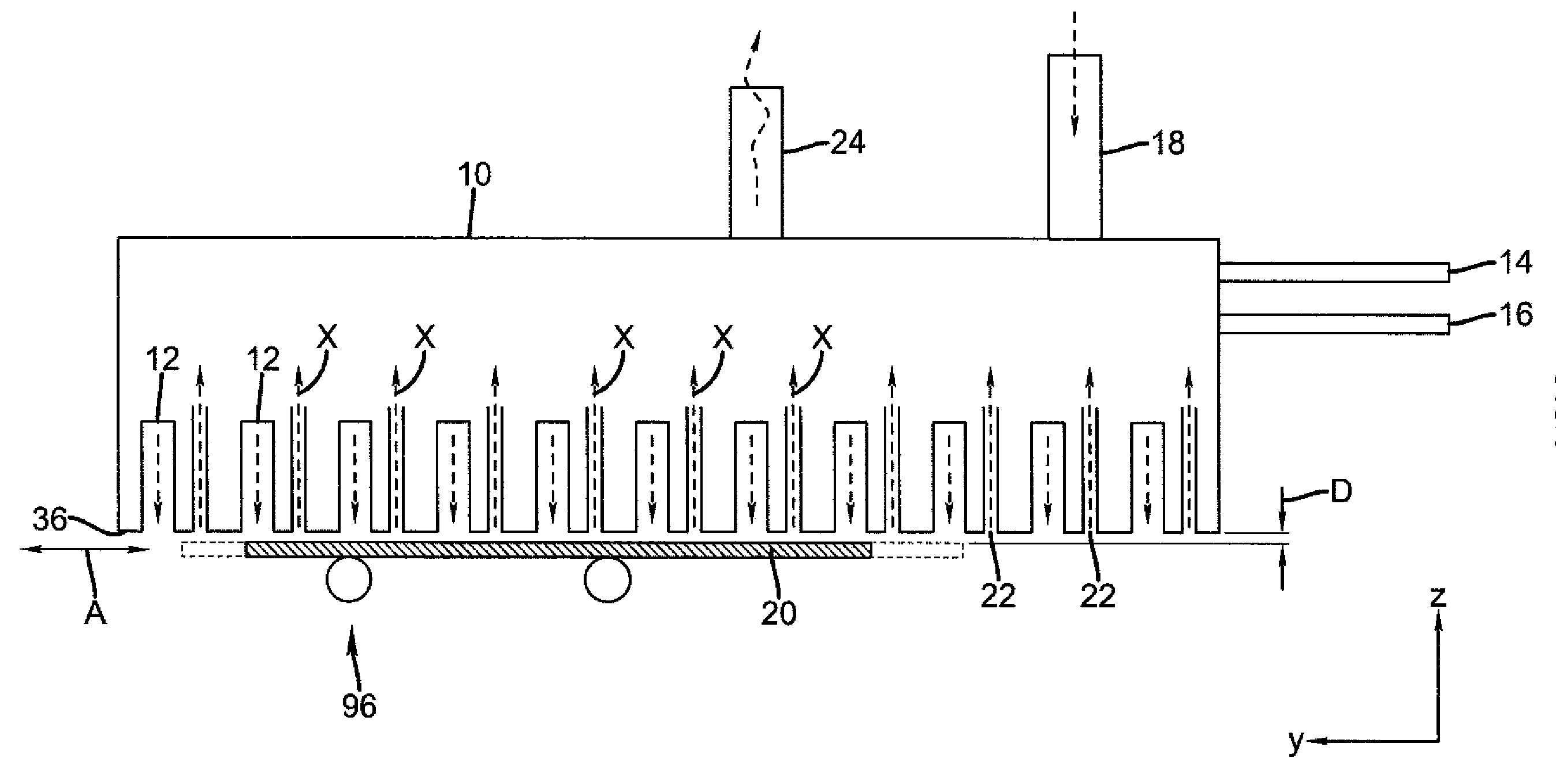
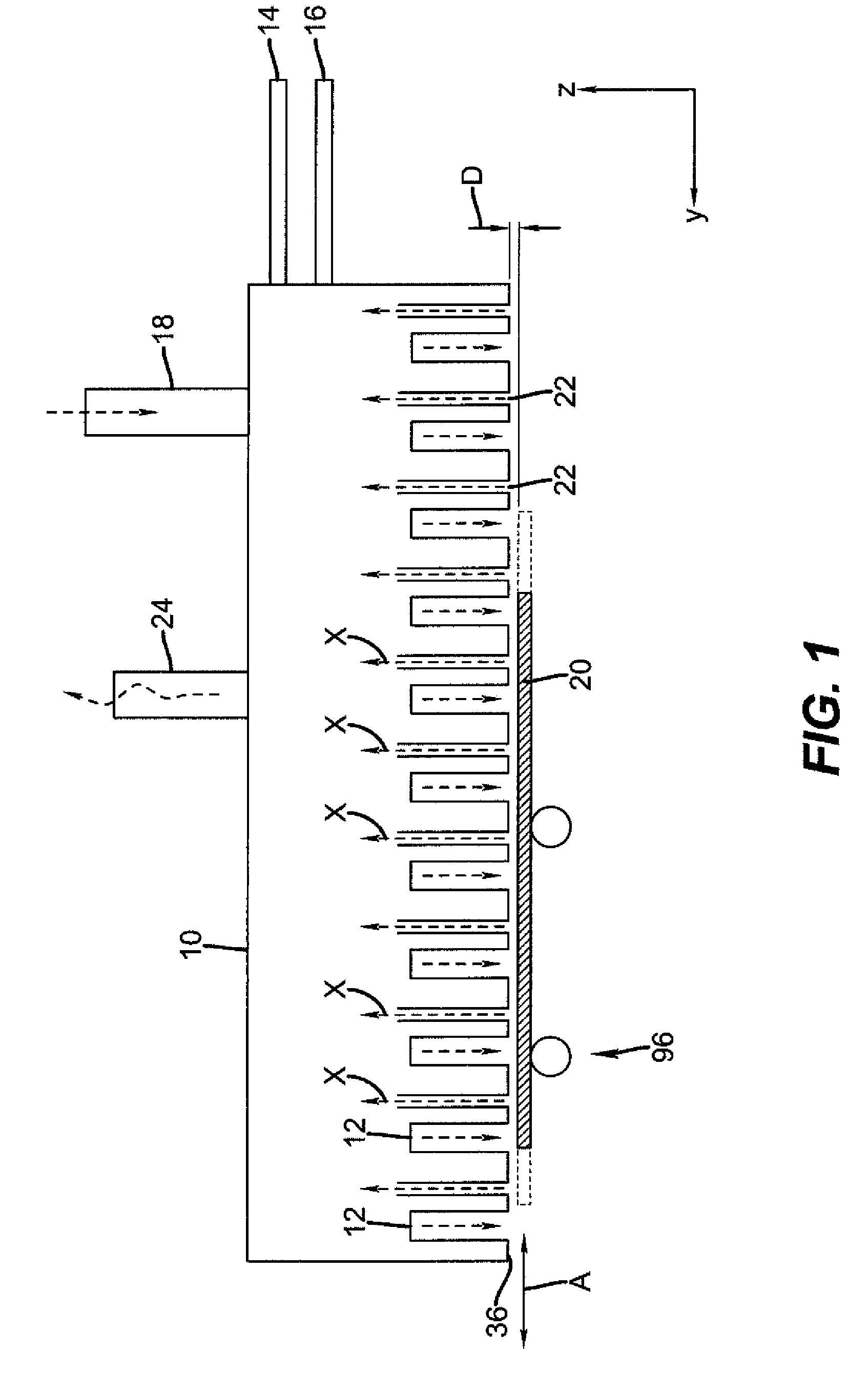
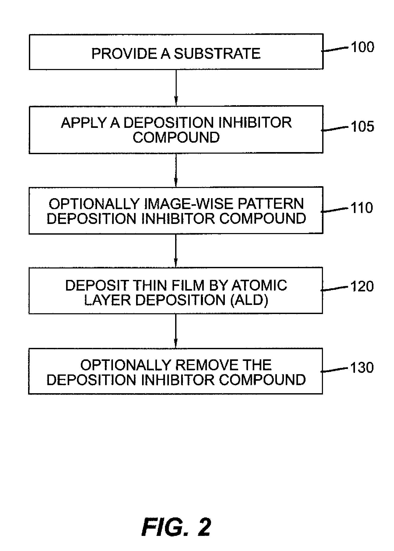
The deposition of amorphous silicon, during the manufacture of transistors, requires relatively difficult or complicated processes such as plasma enhanced chemical vapor deposition and high temperatures (typically about 360° C.) to achieve the electrical characteristics sufficient for display applications.
Such plastics, however, limit device processing to below 200° C.
In spite of the potential advantages of flexible substrates, there are many issues associated with plastic supports when using traditional photolithography during conventional manufacturing, making it difficult to perform alignments of transistor components across typical substrate widths up to one meter or more.
Traditional photolithographic processes and equipment may be seriously impacted by the substrate's maximum process temperature, solvent resistance, dimensional stability, water, and solvent swelling, all key parameters in which plastic supports are typically inferior to glass.
The deposition and photolithography items have high capital costs and preclude the easy use of continuous web-based systems.
In practice in any process it is difficult to avoid some direct reaction of the different precursors leading to a small amount of chemical vapor deposition reaction.
Self-saturating surface reactions make ALD ins...

Method used


Image

  • Process for selective area deposition of inorganic materials
  • Process for selective area deposition of inorganic materials
  • Process for selective area deposition of inorganic materials

Examples


example 1

Selective Area Deposition (SAD) of Al2O3 Dielectric Layer by Siloxane Polymer

[0156]Solutions of Part A and Part B of DEHESIVE 944 vinyl-terminated dimethylsiloxane polymer (“siloxane polymer”) were prepared by dissolving ingredients in a mixture of toluene and heptane according to the formulation specified in Table 2. Equal amount of Parts A and B were then mixed and diluted by a factor of 10 using a mixture of toluene and heptane (33 / 48 ratio) to form the stock solution of the siloxane polymer.

TABLE 2IngredientPart APart BSiloxane Polymer (30% Solid)90.090.0Crosslinker V240.10.0Catalyst OL0.03.0Toluene2000.02000.0Heptane2910.02910.0

[0157]The capability of SAD of Al2O3 by the siloxane polymer was then tested by coating half of a Si wafer with the siloxane-polymer stock solution. Half of the Si wafer was taped off with a Kapton sheet by scotch tape, and the siloxane-polymer stock solution was spun onto the untaped half (3k RPM for 1 min). The tape and KAPTON polymer sheet and tape we...

example 2

Selective Area Deposition (SAD) of ZnO Semiconductor Layer by Siloxane Polymer

[0158]A Si wafer, half side coated with a thin layer of DEHESIVE 944 siloxane polymer as described in Example 1, was subject to ZnO deposition following the same procedure as described in Comparative Example 2. After 300 deposition cycles, a uniform film of ZnO with an average thickness of 565 Å was formed on the un-protected side, but no detectable deposition of ZnO was found on the siloxane-polymer protected side.

example 3

[0159]Selective Area Deposition (SAD) of IZO Semiconductor Layer by Siloxane Polymer

[0160]A Si wafer, with a half side coated with a thin layer of DEHESIVE 944 siloxane polymer as described in Example 1, was subject to InZnO (IZO) deposition following the same procedure as described in Comparative Example 2, except that a flow of trimethylindium vapor was combined with the diethyl zinc flow. The solid trimethylindium (TMI) precursor was contained in a glass bubbler and its vapor was entrained in a flow of nitrogen. The relative ratios of nitrogen flow into the DEZ and TMI bubblers were 13 and 80 sccm, respectively. The Si wafer was maintained at a temperature of 240° C. After 300 deposition cycles, a uniform film of IZO was deposited having an average thickness of 565 Å on the un-protected side, but no detectable deposition of IZO was found on the siloxane-polymer protected side.


PUM

PropertyMeasurementUnit
Temperatureaaaaaaaaaa

Abstract

An atomic-layer-deposition process for forming a patterned thin film comprising providing a substrate, applying a deposition inhibitor material to the substrate, wherein the deposition inhibitor material is an organic compound or polymer; and patterning the deposition inhibitor material either after step (b) or simultaneously with applying the deposition inhibitor material to provide selected areas of the substrate effectively not having the deposition inhibitor material. An inorganic thin film material is substantially deposited only in the selected areas of the substrate not having the deposition inhibitor material.

Description

CROSS-REFERENCE TO RELATED APPLICATIONS[0001]The present application is related to U.S. application Ser. No. 11 / 392,007, filed Mar. 29, 2006 by Levy and entitled, “PROCESS FOR ATOMIC LAYER DEPOSITION,” U.S. application Ser. No. 11 / 392,006, filed Mar. 29, 2006 by Levy and entitled “APPARATUS FOR ATOMIC LAYER DEPOSITION,” U.S. application Ser. No. 11 / 620,738, filed on Jan. 8, 2007 by Levy and entitled “DELIVERY DEVICE FOR DEPOSITION,” U.S. application Ser. No. 11 / 620,740, filed Jan. 8, 2007 by Nelson et al. and entitled “DELIVERY DEVICE COMPRISING GAS DIFFUSER FOR THIN FILM DEPOSITION,” US Application Serial Number ______ (docket 94077), filed concurrently herewith by Kerr et al. and entitled, “DEPOSITION SYSTEM FOR THIN FILM FORMATION,” US Application Serial Number ______ (docket 94217), filed concurrently herewith by Kerr et al. and entitled “DELIVERY DEVICE FOR DEPOSITION,” US Application Serial Number ______ (docket 94079), filed concurrently by Levy et al. and entitled “SYSTEM FO...

Claims


Application Information

Patent Timeline
IPC IPC(8): H01L21/00C23C16/00
CPCC23C16/042C23C16/45551H01L21/02175H01L21/02178H01L51/0004H01L21/02304H01L21/3141H01L21/31616H01L21/0228H10K71/13
Inventor YANG, CHENGIRVING, LYN M.LEVY, DAVID H.COWDERY-CORVAN, PETER J.FREEMAN, DIANE C.
Owner EASTMAN KODAK CO
Why Eureka
Try Eureka