

Nanoparticle coated electrode and method of manufacture
a technology of nanoparticles and electrodes, applied in the direction of electrochemical generators, electrochemical coatings, cell components, etc., can solve the problems of high cost of particle filters, large expenditure of fleet owners in replacing older diesel engines with new engines, and low pollution of fuel cells, etc., to achieve good connection, increase the rate of electrochemical reaction, and enhance the surface area
- Summary
- Abstract
- Description
- Claims
- Application Information
AI Technical Summary
Benefits of technology
Problems solved by technology
Method used
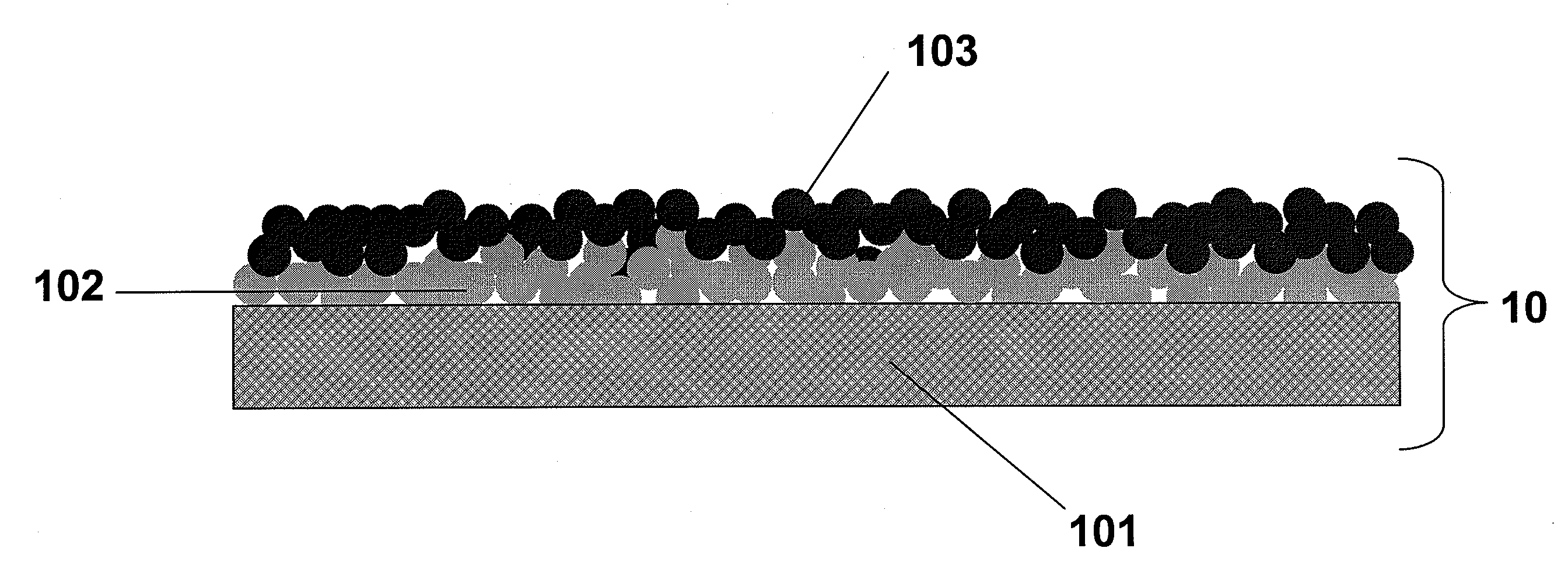
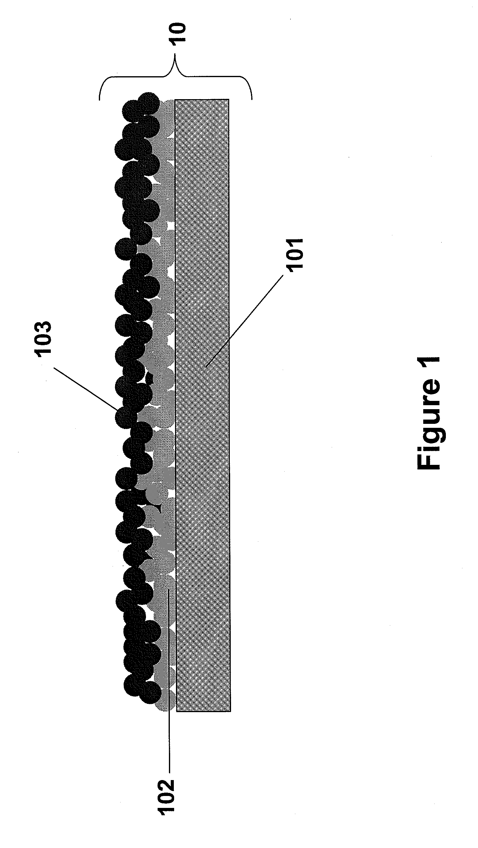
Image

Examples
example 1
Preparation of a Nanoparticle Electrode
[0029]About 2 grams of nano-silver powder was blended into 5 grams of ethylene glycol. The resulting primary nanoparticle dispersion was stirred for five minutes. Nickel was cut to the desired electrode shape and coated with the dispersion. The nickel with silver layer was heated to evaporate off the solvent and allowed to cool. The process was repeated an additional 3-4 times. After the final primary layer was applied, the coated nickel plate was placed in a furnace at 900° C. for one hour and then allowed to cool. A second metal nanoparticle dispersion was prepared by combining 0.5 grams of nano nickel particles with 0.5 grams of nano iron particles into 3 grams of ethylene glycol. The resulting dispersion was stirred for five minutes. The metallic plate coated with the primary nanoparticle coating was layered with this dispersion. The secondary nanoparticle layer was heated to evaporate off the solvent and allowed to cool. The process was r...
example 2
Electrode Performance
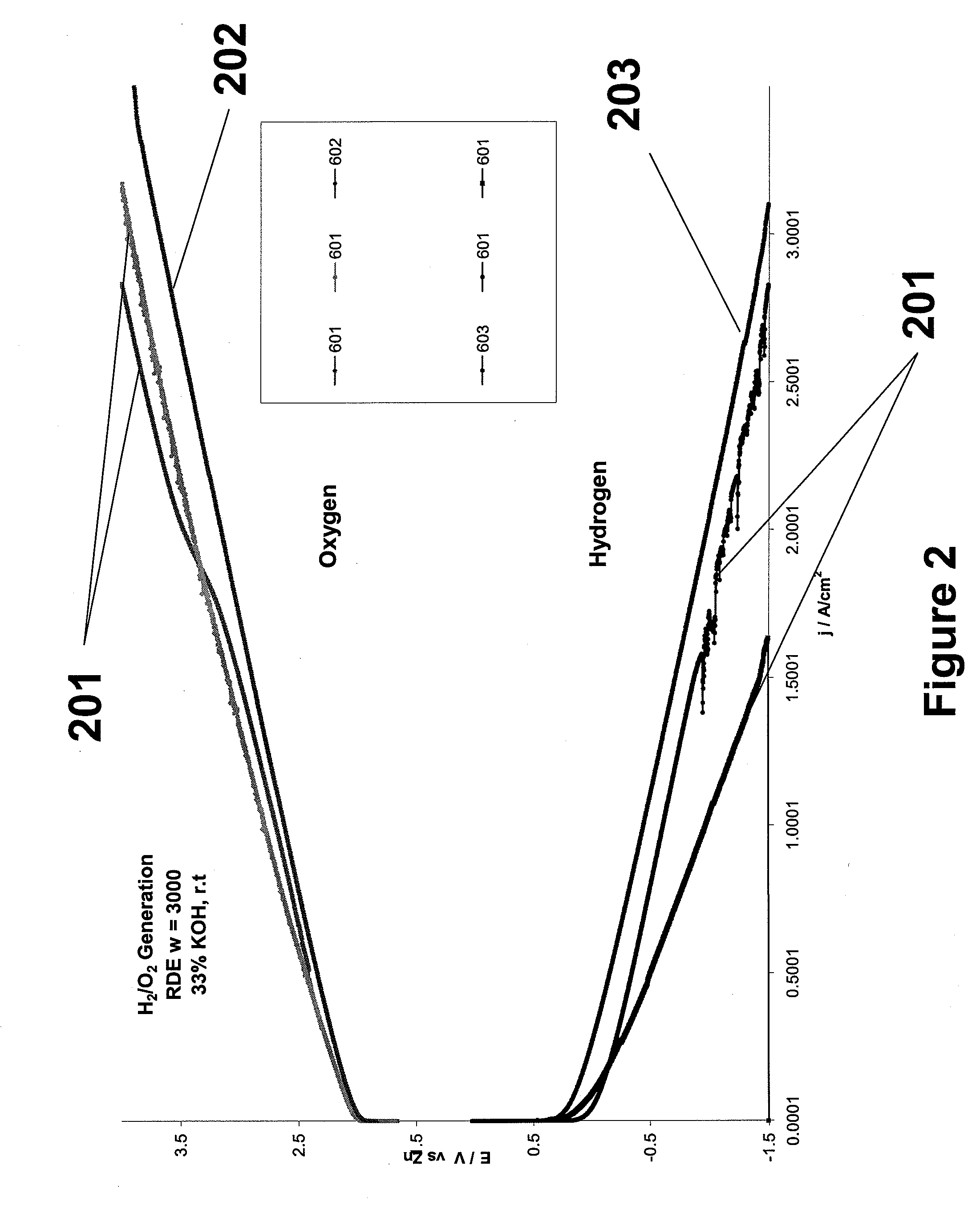
[0030]Cathodes were tested using a half-cell apparatus to independently test the electrode activity for hydrogen and oxygen generation. Electrolyte was a 33% KOH solution against a zinc-wire reference electrode. FIG. 2 shows a set of galvanostatic tests at 1 A / cm2 for oxygen generation and a set for hydrogen generation. The most inefficient electrodes, shown as lines 201 are the lowest and highest lines on the hydrogen and oxygen curves, respectively. The most efficient electrodes were the nanoparticle coated electrodes. Lines 202 and 203 illustrate this enhanced performance.
PUM
| Property | Measurement | Unit |
|---|---|---|
| Temperature | aaaaa | aaaaa |
| Temperature | aaaaa | aaaaa |
| Diameter | aaaaa | aaaaa |
Abstract
Description
Claims
Application Information