Production method for metal matrix composite material

a metal matrix and composite material technology, applied in the direction of coatings, etc., can solve the problems of significant deterioration in sinterability and plastic workability, difficult or substantially impossible to roll cladded materials, and difficult or substantially impossible to roll them, so as to facilitate cold plastic work and high filling rate , the effect of enhancing the rollability

Active Publication Date: 2009-04-23
NIPPON LIGHT METAL CO LTD +1
View PDF8 Cites 4 Cited by
  • Summary
  • Abstract
  • Description
  • Claims
  • Application Information

AI Technical Summary

Benefits of technology

[0087]The mixed powder in the pre-heated assembly to be subjected to the rolling process is maintained in powder form without being solidified. That is, the mixed powder is not subjected to a preforming process for allowing a mixed powder to be maintained in a predetermined shape, specifically a process of preforming a mixed powder in an intended shape through press working or pulse-current pressure sintering. In the present invention, although the mixed powder is packed in the pre-rolling assembly at a relatively high filling rate, the filling rate is not increased to a level allowing the mixed powder to be changed from the powder state.
[0088]In addition, when the mixed powder M maintained in powder form is subjected to the rolling process, it is sandwiched by metal or aluminum members from above and below. Specifically, a top surface of the mixed powder M is covered by the top wall 14E of the upper casing 14 fully and tightly, and a bottom surface of the mixed powder M is covered by the bottom wall 12E of the lower casing 12 fully and tightly. In this manner, the pre-rolling assembly 18 having the mixed powder M hermetically sealed in the casing 10 and sandwiched by the aluminum members from above and below is provided as a raw material of a plate-shaped cladded material.
[0089]The preheated assembly 18 is typically subjected to rolling and formed in an intended shape. In case of forming the preheated assembly 18 in a plate shape, a plate-shaped cladded material having a given clad rate of an Al plate and / or an Al casing can be obtained only through cold rolling. In hot plastic working, a single plastic working may be performed, or plural types of plastic workings may be performed in combination. Alternatively, after hot plastic working, cold plastic working may be performed. In case of performing cold plastic working, before the cold plastic working, the pre-rolling assembly may be subjected to annealing at a temperature of 300 to 600° C. (preferably 400 to 500° C.) to facilitate the cold plastic working.
[0090]The pre-rolling assembly 18 is cladded with the aluminum plates, and therefore a surface of the pre-rolling assembly 18 is free from ceramic particles which act as a fracture origin during plastic working and cause accelerated wear of a roll, die or the like. This makes it possible to provide enhanced rollability and obtain an aluminum matrix composite material excellent in strength and surface texture. In addition, an obtained hot plastic-worked product has a surface cladded with metal, and the metal clad is tightly bonded with the inner mixed powder M. Thus, the hot plastic-worked product is superior in corrosion resistance, impact resistance and thermal conductivity to an aluminum matrix composite material devoid of metal cladding a surface thereof.
[0091]In another preferred embodiment, before rolling, a surface of the pre-rolling assembly 18 is effectively covered by a protective plate, such as a thin plate made of SUS or Cu. This makes it possible to prevent occurrence of longitudinal (frontward / rearward) wrinkling or cracking which is likely to arise during plastic working.
[0092]More specifically, in the rolling process, the preheated assembly 18 is subjected to hot rolling at a draft (i.e., rolling reduction) ranging from 10 to 70%. A rolling temperature in the hot rolling is set at approximately 500° C.

Problems solved by technology

Although each of the functions can be enhanced by increasing an amount of ceramic additives having the respective functions, an approach of simply increasing the amount of ceramic additives will cause significant deterioration in sinterability and plastic workability, such as, extrudability, rollability or forgeability.
In reality, this technique is likely to involve problems about insufficiency of the impregnation with the molten aluminum alloy, and occurrence of defects, such as shrinkage during solidification of the molten aluminum alloy.
The reason is that it is difficult or substantially impossible to roll the cladded material unless it is performed by sintering in such a manner as to be maintained in a predetermined shape.
As described above, it is essential for WO 2006 / 070879 to preform the cladded material in such a manner as to be maintained in a predetermined shape, i.e., to subject the mixed powder to pulse-current pressure sintering, which leads to deterioration in process efficiency and difficulty in achieving an intended cost reduction.

Method used


Image

  • Production method for metal matrix composite material
  • Production method for metal matrix composite material
  • Production method for metal matrix composite material

Examples


first embodiment

[0043]The following description will be made about raw materials and then about the production process, in a method according to a first embodiment of the present invention.

[0044](1) Raw Materials

[0045]Aluminum Powder Serving as the Matrix

[0046]In a preferred embodiment, an aluminum powder serving as a matrix is made of an Al based alloy, specifically an aluminum alloy defined as A 1100 by JIS (or AA 1100 by A.A.). More specifically, the aluminum powder comprises 0.25 weight % or less of silicon (Si), 0.40 weight % or less of iron (Fe), 0.05 weight % or less of copper (Cu), 0.05 weight % or less of manganese (Mn), 0.05 weight % or less of magnesium (Mg), 0.05 weight % or less of chromium (Cr), 0.05 weight % or less of zinc (Zn), 0.05 weight % or less of vanadium (V) and 0.03 weight % or less of titanium (Ti), with the remainder being aluminum (Al) and inevitable impurities.

[0047]The aluminum powder in the present invention is not limited to the above specific composition. For exampl...

example 1

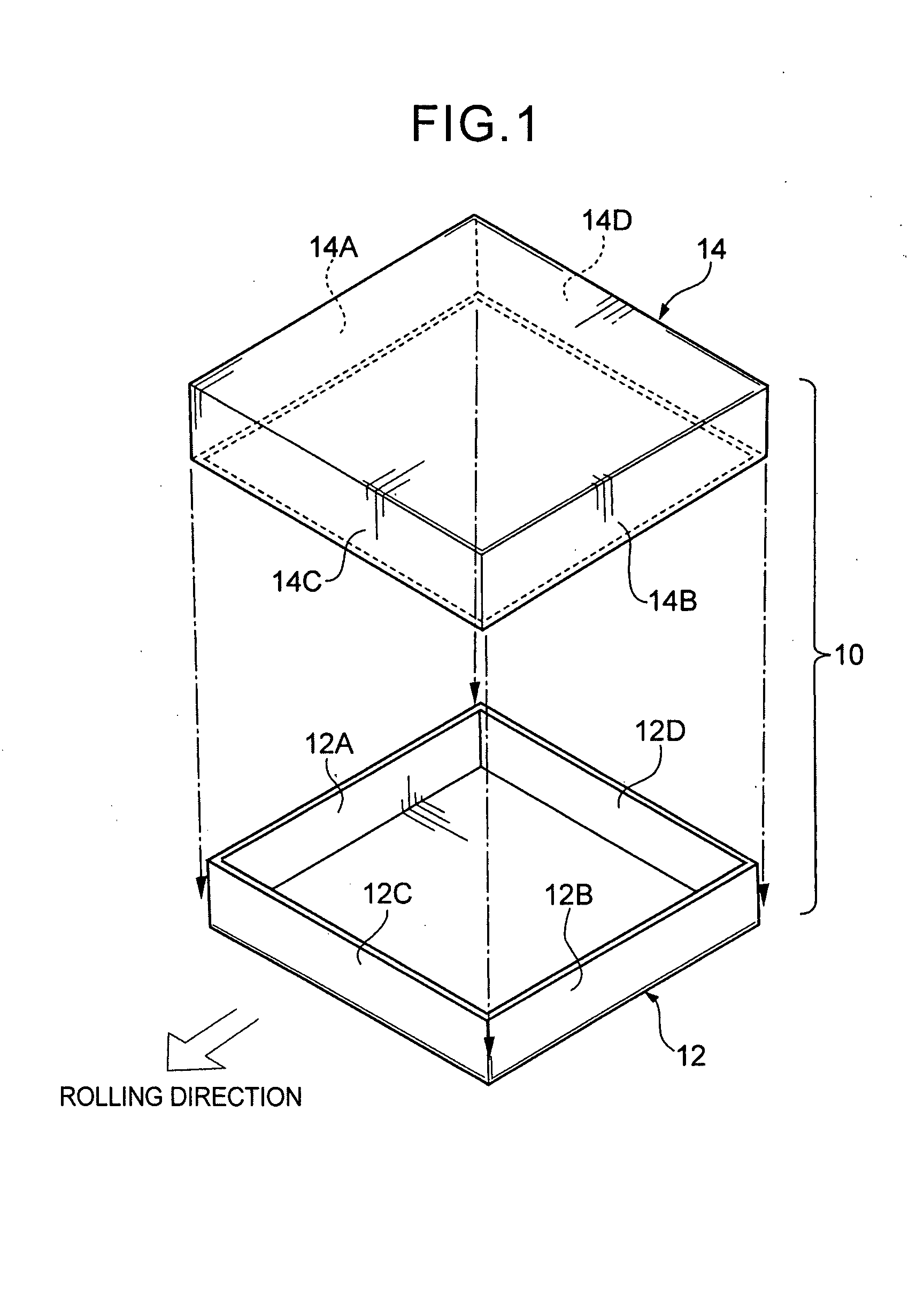
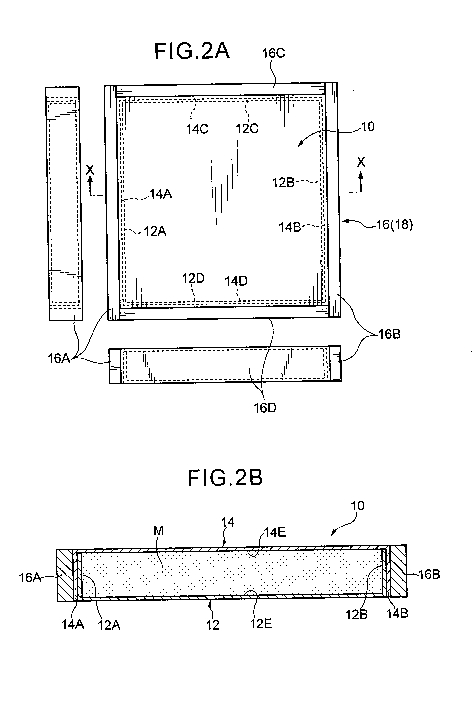
[0104]A B4C ceramic powder was uniformly mixed with an aluminum alloy powder having a composition as shown in Table 1, in an amount of 35 mass %, to prepare a mixed powder M. Then, a lower casing 12 made of an aluminum alloy (JIS A5052P) and formed in an approximately rectangular parallelepiped shape having outside dimensions of 367.7 mm on a side in square-shaped top and bottom surfaces, and 31.6 mm in height, and a wall thickness of 1.6 mm was prepared. Further, an upper casing 14 made of an aluminum alloy (JIS A5052P) and formed in an approximately rectangular parallelepiped shape having outside dimensions of 370.9 mm on a side in square-shaped top and bottom surfaces, and 33.2 mm in height, and a wall thickness of 1.6 mm was prepared. The aluminum alloy (JIS A5052P) had a tensile strength of 195 MPa.

TABLE 1SiFeCuMnMgCrZnVTiAl0.25%0.40%0.05%0.05%0.05%0.05%0.05%0.05%0.05%remainderor lessor lessor lessor lessor lessor lessor lessor lessor less

[0105]Two aluminum plates each formed t...

example 2

[0111]In order to clarify an optimal range of the width of the reinforcing frame 16, in addition to the reinforcing frame 16 in the Example 1 having a width of 20.0 mm, five types of reinforcing frames 16 were prepared by changing only the width to 5 mm, 10 mm, 15 mm, 30 mm and 40 mm. Except for this change, the product was made under the same conditions as those in the Example 1. Each of the prepared reinforcing frames 16 was welded to the pre-rolling assembly 18 to prepare five types of samples, and each of the samples was subjected to rolling in the same manner.

[0112]Further, an additional five types of reinforcing frames 16 were prepared by changing the material of the reinforcing frame 16 in the Example 1 to an aluminum alloy (JIS A6063) and then changing only the width to 5 mm, 10 mm, 15 mm, 30 mm and 40 mm. Except for these changes, the product was made under the same conditions as those in the Example 1. Each of the prepared reinforcing frames 16 was welded to the pre-rollin...


PUM

PropertyMeasurementUnit
temperatureaaaaaaaaaa

Abstract

A method of producing an aluminum matrix composite material is described that comprises the steps of: mixing an aluminum powder and a ceramic powder to prepare a mixed powder; providing a lower casing made of aluminum and formed in a hollow rectangular parallelepiped shape having an open top, and a closing member made of aluminum and formed in a shape adapted to hermetically close the open top of the lower casing; packing the mixed powder into the lower casing; closing the open top of the lower casing filled with the mixed powder, by the closing member, to prepare a pre-rolling assembly having the mixed powder hermetically sealed therein; preheating the pre-rolling assembly; and rolling the preheated assembly to obtain the aluminum matrix composite material, where the aluminum matrix composite material includes a pair of metal plates having the mixed powder therebetween.

Description

BACKGROUND OF THE INVENTION[0001]1. Field of the Invention[0002]The present invention generally relates to a production method for a metal matrix composite material. More specifically, the present invention relates to a production method for a metal matrix composite material excellent in properties, such as plastic workability, thermal conductivity, room-temperature or high-temperature strength, high stiffness, neutron absorption performance, wear resistance and low thermal expansibility.[0003]2. Description of the Related Art[0004]Heretofore, there has been known a method of producing a composite material having an aluminum matrix through a powder metallurgy process, comprising the steps of:[0005](1) mixing a powder of a ceramic material serving as a reinforcing material, such as Al2O3, SiC, B4C, BN, aluminum nitride or silicon nitride, with an aluminum powder serving as a matrix;[0006](2) subjecting the mixed powder to canning or cold compaction to form a compact;[0007](3) subject...

Claims


Application Information

Patent Timeline
Patent Type & Authority Applications(United States)
IPC IPC(8): B22F7/04
CPCB22F7/04B22F2003/185C22C32/0047C22C32/00C22C29/14C22C29/062C22C29/005C22C1/1084B22F2999/00B22F2998/10C22C1/10B22F3/1216B22F3/16B22F3/02B22F3/18B22F2003/248
Inventor TAMAKI, YUICHISANADA, KAZUTONISHIYAMA, TOSHIMASA
Owner NIPPON LIGHT METAL CO LTD
Why Eureka
Try Eureka