Nanomaterial facilitated laser transfer

a technology of nanomaterials and lasers, applied in nanoinformatics, nanotechnology, transportation and packaging, etc., can solve the problems of introducing contamination into the deposited material, affecting the deposition process, and affecting the deposition effect, so as to facilitate the deposition/removal

Inactive Publication Date: 2009-05-21
RGT UNIV OF CALIFORNIA +1
View PDF21 Cites 55 Cited by
  • Summary
  • Abstract
  • Description
  • Claims
  • Application Information

AI Technical Summary

Benefits of technology

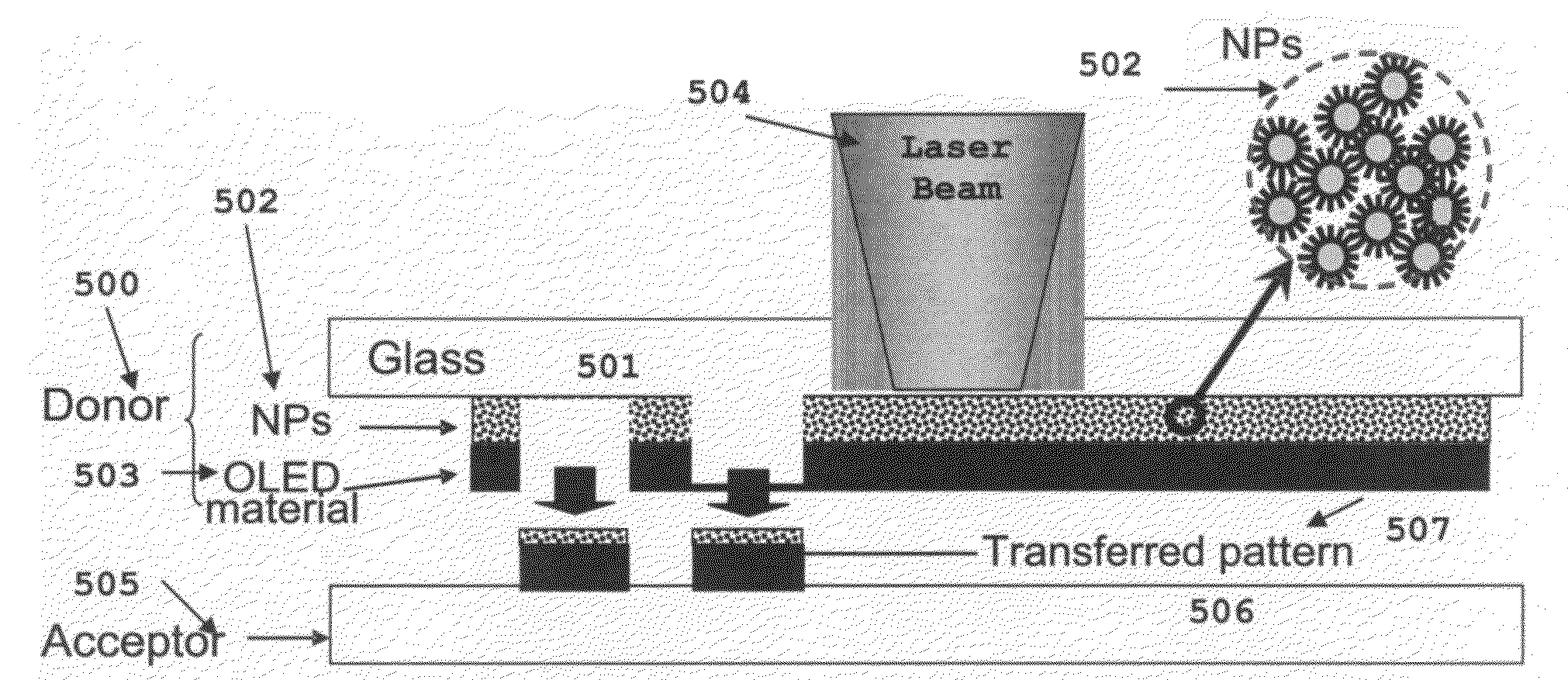
[0013]Accordingly and advantageously the present invention relates to methods, materials, systems, and / or devices for the deposition and / or removal of a material of interest onto and / or from a substrate using one or more nanomaterials and / or nanoparticles to enable or to facilitate the deposition / removal. Some embodiments of the present invention relate to methods for the deposition of a material on a substrate without the use of a mask. Some embodiments of the present invention relate to methods for the deposition of a wide range of materials on a substrate wherein typical materials may include metals, metal alloys, metal compounds, inorganic dielectric layers, organic dielectric layers, inorganic semiconductor layers, organic semiconductor layers, organic conducting layers, polymers, glasses, and ceramics, among others. Some embodiments of the present invention relate to methods for the deposition of a material on a substrate using an energy source wherein typical energy sources may include a pulsed laser, a continuous wave laser, a pulsed lamp, a continuous wave lamp, and an LED, among others. Some embodiments of the present invention relate to methods for the deposition of a material on a substrate wherein at least a portion of the deposited material forms some or all of the desired pattern. Some embodiments of the present invention relate to methods for the removal of a material from a substrate wherein the material remaining on the substrate after removal forms some or all of the desired pattern.

Problems solved by technology

Many of the direct write technologies exhibit a number of limitations.
The liquid must be removed during a later processing step and the liquid removal may introduce contamination into the deposited material.
The laser-based techniques also exhibit a number of limitations.
Laser-based techniques have been previously investigated for the deposition of organic materials with limited success.
Generally, organic compounds have high vapor pressures and are easily damaged by high temperatures.
The damage may be caused by the direct thermal decomposition or degradation of the organic material, or may be caused by the reaction of the organic material with gaseous species in the environment at elevated temperatures.
All such factors tend to limit the manufacturing techniques that may be employed.
Traditional lithography and thermal evaporation deposition techniques have significant disadvantages, among which is the need for masks which are typically difficult to make to the required specifications at a reasonable price.

Method used


Image

  • Nanomaterial facilitated laser transfer
  • Nanomaterial facilitated laser transfer
  • Nanomaterial facilitated laser transfer

Examples


example 1

[0048]In this example, the target deposition material of interest was chosen as an organic material (tris-(8-hydroxyquinoline)Al) (Alq3). Alq3 is an organic material commonly used in the manufacture of OLED displays. The light absorption material was formed from Ag nanoparticles having sizes in the range from about 30 nm to about 40 nm in diameter and protected with an organic SAM coating. The SAM coating may be applied to the Ag nanoparticles by a well known two-phase reduction method as discussed, for example, by Hostetler et al, Langmuir 1998, Vol. 14(1), pp. 17-30 (1998), the entire contents of which is incorporated herein by reference for all purposes. Aqueous metal salts are mixed in a toluene solution containing long-chain alkylammonium surfactants to form a two-phase system. Vigorous stirring for about 1 hour to about 3 hours transfers the metal salts into the organic phase, which is then separated. A measured quantity of surface monolayer, hexanethiol is added to the organi...

example 2

[0054]Donor and acceptor surfaces were prepared as described in Example 1 and different transfer conditions and patterns were investigated.

[0055]FIGS. 7a-f are photographs of the Alq3 layers under UV illumination. FIG. 7a contains a photograph of the first surface of the acceptor substrate after laser irradiation and material transfer. The green letters “UCB” and the star shapes correspond to regions where the laser irradiation resulted in the transfer of the Alq3 material from the donor substrate to the acceptor substrate. The “UCB” letters were formed from combining the 0.9 mm by 0.9 mm square shapes discussed in Example 1. The star shapes were formed by projecting the laser beam through a mask containing star shapes before the laser beam reached the donor substrate structure. The fluorescence of the Alq3 shapes provides strong evidence that the transferred Alq3 layer was not significantly damaged by the transfer process.

[0056]In FIG. 7a, the line of stars indicated at (i) was pat...

example 3

[0059]Donor and acceptor surfaces were prepared as described in Example 1 and different transfer conditions and patterns were investigated.

[0060]FIGS. 8a-f contain photographs of the Alq3 layers under UV illumination. FIG. 8a contains a photograph of the first surface of the acceptor substrate after laser irradiation and material transfer. The green letters “LTL” and the star shapes correspond to regions where the laser irradiation resulted in the transfer of the Alq3 material from the donor substrate to the acceptor substrate. The “LTL” letters were formed by combining 0.9 mm by 0.9 mm square shapes discussed in Example 1. The star shapes were formed by projecting the laser beam through a mask containing star shapes before the laser beam reached the donor substrate structure. The fluorescence of the Alq3 shapes is strong indication that the transferred Alq3 layer was not damaged by the transfer process. In FIG. 8a, the line of stars indicated at (i) was patterned using a laser puls...


PUM

PropertyMeasurementUnit
diametersaaaaaaaaaa
absorption depthaaaaaaaaaa
thicknessaaaaaaaaaa

Abstract

The invention relates to the deposition or transfer of material using a laser induced forward transfer process. More specifically, the invention relates to the transfer of material using a laser induced forward transfer process wherein the transfer process is facilitated or enabled by nanomaterials. Nanomaterials in the form of nanoparticles or nanofilms may be employed, optionally including a surface coating or self-assembled monolayer surface coating, making use of properties of the nanomaterials that allow the laser induced forward transfer process to be practiced at irradiation energies and temperatures lower than commonly used. The technique may be well suited for depositing organic layers.

Description

CROSS-REFERENCE TO RELATED APPLICATIONS[0001]This application claims priority pursuant to 35 USC § 119 from provisional patent application Ser. No. 60 / 999,864 filed Oct. 22, 2007, the entire contents of which is incorporated herein by reference for all purposes.BACKGROUND OF THE INVENTION[0002]1. Field of Invention[0003]The invention relates to the deposition or transfer of material using a laser induced forward transfer process. More specifically, the invention relates to the transfer of material using a laser induced forward transfer process wherein the transfer process is facilitated by one or more nanomaterials.[0004]2. Description of the Prior Art[0005]Many technologies are enabled, facilitated or improved by the ability to pattern a wide variety of materials for specific purposes. A few examples of such technologies include microelectronics, flexible electronics, printed circuit boards, solar cells, liquid crystal displays (LCD), light emitting diodes (LED), and organic light ...

Claims


Application Information

Patent Timeline
Patent Type & Authority Applications(United States)
IPC IPC(8): B32B5/16
CPCB41M5/42B41M2205/38B82Y10/00H01L51/0013Y10T428/25H05K3/046H05K2201/0257H05K2203/0528H05K2203/107H01L51/0081C23C14/048H10K71/18H10K85/324
Inventor GRIGOROPOULOS, COSTAS P.KO, SEUNG H.PARK, HEE K.
Owner RGT UNIV OF CALIFORNIA
Why Eureka
Try Eureka