
Measuring nitrogen oxides and other gases by ozone formation

a technology of nitrogen oxides and other gases, applied in the field of nitrogen oxide measurement, can solve the problems of adding significant weight and cost to these instruments, ozone depletion methods are susceptible to interference by any species, and chemiluminescent methods require calibration with expensive standards of no gas, etc., to achieve the effect of reducing the requirement for recalibration, reducing the cost of components, and reducing the weight and cost of instruments

Inactive Publication Date: 2009-05-28
BOGNAR JOHN A
View PDF1 Cites 267 Cited by
  • Summary
  • Abstract
  • Description
  • Claims
  • Application Information

AI Technical Summary

Benefits of technology

[0022]In addition, an exemplary embodiment of the invention, by operating in a pulsed mode, has a major sensitivity advantage in that pulsed or modulated signals can be retrieved, isolated, and amplified by instrumental means with a much higher signal-to-noise ratio than can be achieved with non-pulsed methods. This benefit of pulsing or chopping a signal is well-known and often used to isolate very small signals on top of large background signals. By operating in this rapid pulsed mode, the exemplary method can be insensitive to instrumental changes occurring over comparatively long timescales, such as lamp fluctuations, thermal expansion, ozone source fluctuations and the like.
[0023]Recalibration requirements are also reduced as the measurement is based on absorption of ultraviolet light by ozone, which can be quantitatively related to the concentration of ozone via the known absorption cross-section of ozone. The quantitative relationships between NO, NO2, and ozone in the instrument lead to a system that can be self-calibrating, thereby eliminating the need for compressed gas cylinders containing standard concentrations of nitric oxide to support the routine use of the instrument.
[0024]There are significant advantages for the medical applications of the device described herein as the device addresses many of the issues that have caused competitive NO devices to be commercially unsuccessful. Some of the exemplary advantages of this nitric oxide device in medical applications include: inexpensive components, ease of calibration, and, if the device is used in the medical field, other than mouthpieces, the device has no disposable parts, such as expensive disposable sensors for measuring nitric oxide. Additionally, the instrument is unaffected by humidity, carbon dioxide, or other gases such as terpenes that can affect ozone depletion measurement of nitric oxide. The instrument can also be lightweight and portable.

Problems solved by technology

The chemiluminescent method depends upon providing a low-pressure region so that the excited NO2* is not quenched but instead releases a photon; the attendant requirement for a vacuum chamber and vacuum pump adds significant weight and cost to these instruments.
In addition, the chemiluminescent method requires calibration with expensive standards of NO gas.
The ozone depletion method is susceptible to interference by any species which reacts with ozone, not just NO.
In contrast, the ozone depletion method of Birks et al relies on accurate absolute measurements of total ozone concentration, which can lead to a susceptibility to errors as well as interference of gases, such as terpenes in the atmosphere which can combine with ozone.
Furthermore at typical ozone concentrations used in this method, the NO and ozone reaction will be slow.
As a result, the ozone depletion method by necessity may only operate at relatively low speeds in comparison to the described exemplary method.
The method of Birks et al also does not allow for the direct measurement of nitrogen dioxide.
Additionally, the instrument is unaffected by humidity, carbon dioxide, or other gases such as terpenes that can affect ozone depletion measurement of nitric oxide.

Method used


Image

  • Measuring nitrogen oxides and other gases by ozone formation
  • Measuring nitrogen oxides and other gases by ozone formation
  • Measuring nitrogen oxides and other gases by ozone formation

Examples


Embodiment Construction

[0041]The exemplary systems and methods of this invention will be described in relation to photolyzing one or more gases. However, to avoid unnecessarily obscuring the present invention, the following description omits well-known structures and devices that may be shown in block diagram form, are generally known or are otherwise summarized. For purposes of explanation, numerous specific details are set forth in order to provide a thorough understanding of the present invention. It should however be appreciated that the present invention may be practiced in a variety of ways beyond the specific detail set forth herein.

[0042]The term “module” as used herein refers to any known or later developed hardware, software, or combination of hardware and software that is capable of performing the functionality associated with that element. Also, while the invention is described in terms of exemplary embodiments, it should be appreciated that individual aspects of the invention can be separatel...


PUM


Abstract

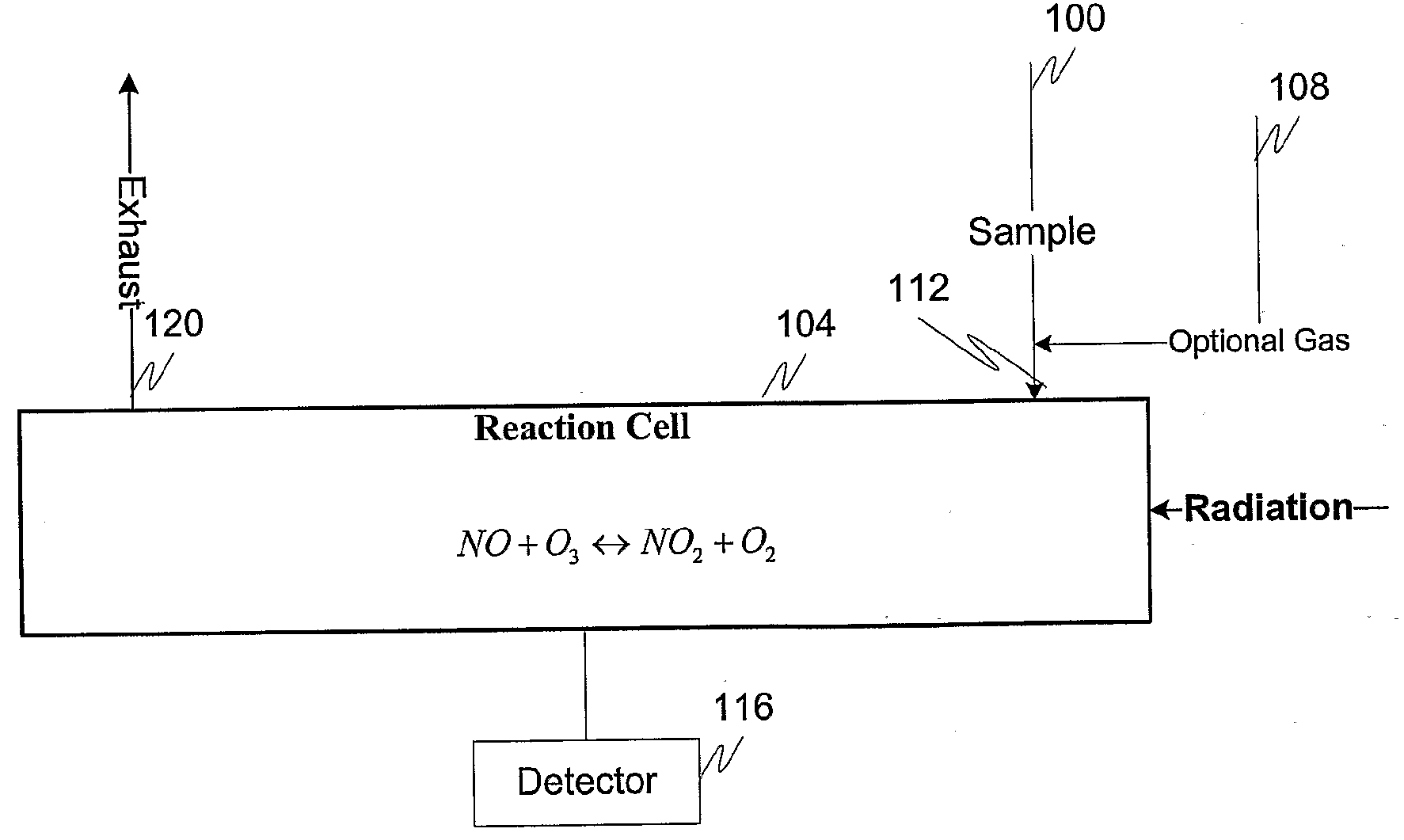
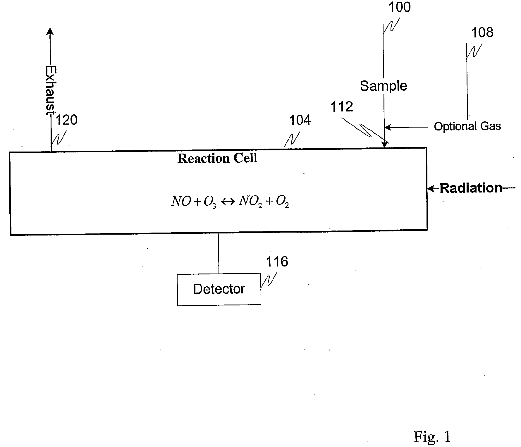
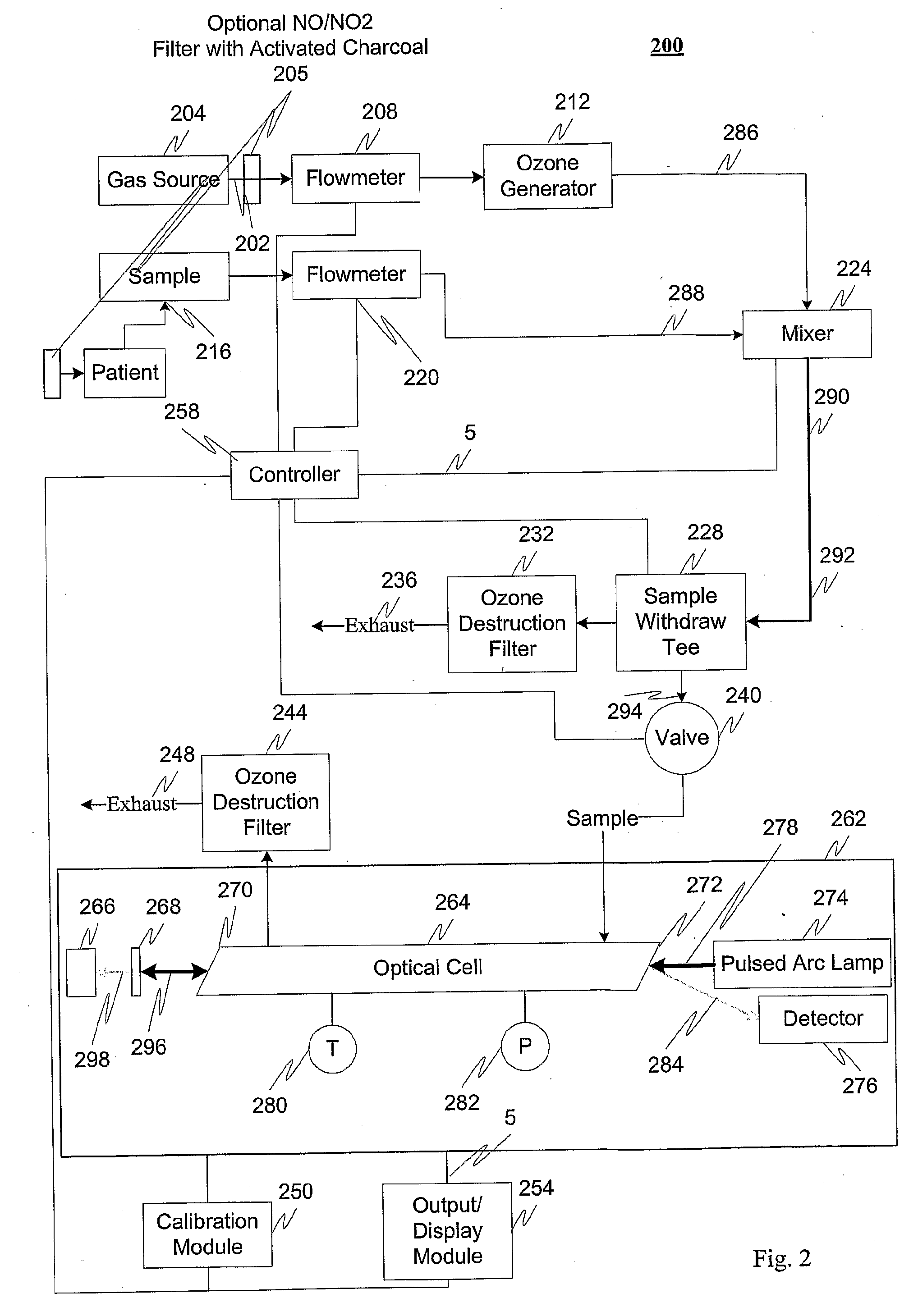
A photochemical sensing system enables the measurement of nitrogen oxides (nitrogen dioxide and nitric oxide) by photolyzing nitrogen dioxide to form oxygen atoms which combine with oxygen molecules to form ozone. Ozone reacts with nitric oxide to for nitrogen dioxide-decreasing ozone. Changes in ozone concentration are measured as a surrogate for the nitrogen dioxide and nitric oxide. Any species which photolyzes to yield oxygen atoms may be measured by this technique. Additional specificity for nitrogen oxides is conferred by allowing the nitric oxide to react with the ozone to recreate the nitrogen dioxide. By periodically photolyzing the nitrogen dioxide (to form ozone), and then allowing the resulting nitric oxide to react with the ozone (thereby reducing ozone), a pulsed signal is obtained whose amplitude is proportional to the total amount of nitrogen dioxide and nitric oxide present. Medical applications include measuring nitric oxide concentrations in expired air samples.

Description

RELATED APPLICATION DATA[0001]This application claims the benefit of and priority under 35 U.S.C. § 119(e) to U.S. Patent Application No. 60 / 722,306, filed Sep. 30, 2005, entitled “Method and Apparatus to Measure Nitrogen Oxides and Other Gases by Ozone Formation,” which is incorporated herein by reference in its entirety.BACKGROUND[0002]1. Field of the Invention[0003]An exemplary embodiment of the invention is related to measurement of nitrogen oxides. More specifically, an exemplary embodiment of the invention is directed toward lightweight, inexpensive instruments that may be used for trace-level measurements of nitrogen oxides in, for example, atmospheric research, fields including medical research and diagnosis and vehicle exhaust measurement, and the like.[0004]2. Description of Related Art[0005]Previous gas-phase, trace-level measurements of nitrogen oxides have focused on the reaction of nitric oxide, NO, with ozone:NO+O3→NO2*+O2 [0006]The resulting nitrogen dioxide is initi...

Claims


Application Information

Patent Timeline
IPC IPC(8): G01N21/00G01N33/00A61B5/08
CPCY10T436/179228G01N33/0037Y02A50/20
Inventor BOGNAR, JOHN A.
Owner BOGNAR JOHN A
Learn More