Methods and Apparatus for Locating Body Vessels and Occlusions in Body Vessels

a technology of body vessels and occlusions, applied in the field of methods and, can solve the problems of inability to locate body vessels, inability to treat patients through traditional surgical techniques, and high cost to society, and achieve the effects of reducing the risk of cabg surgery

Inactive Publication Date: 2009-05-28
MEDTRONIC INC
View PDF0 Cites 119 Cited by
  • Summary
  • Abstract
  • Description
  • Claims
  • Application Information

AI Technical Summary

Benefits of technology

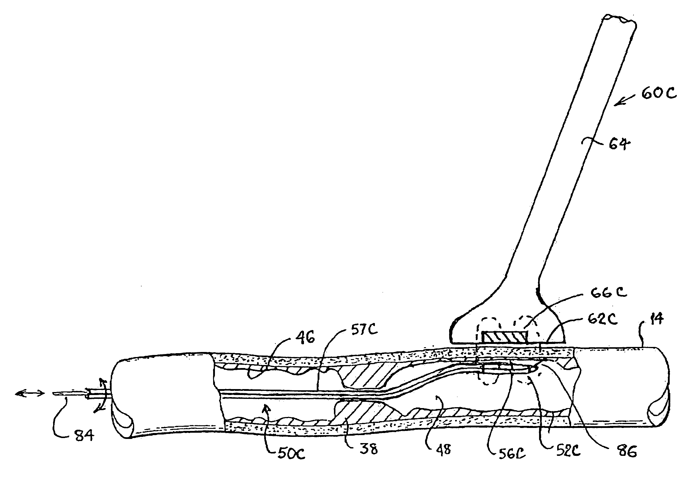
[0058]If the outer surface exposed in the surgical field can be observed by the surgeon directly or employing an endoscope or the like, it may be possible for the surgeon to observe the emitted light direction and intensity. Consequently, this embodiment of the vessel lumen probe can have a second utility independent of interaction with the photosensor.
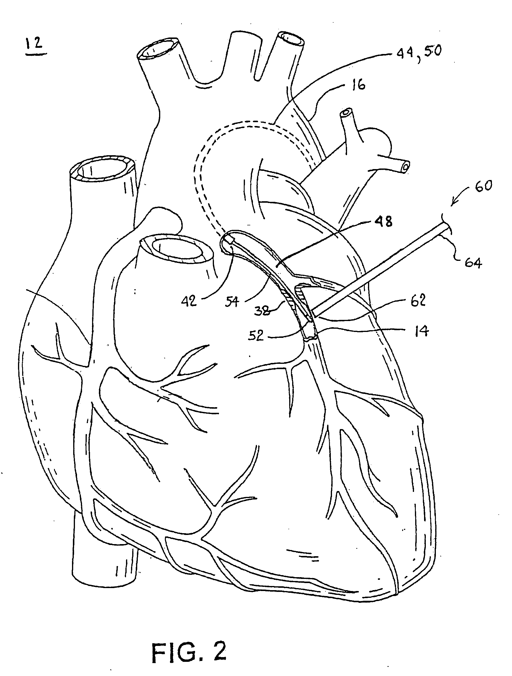
[0061]These various embodiments of the present invention can also be of use in medical or surgical procedures that require avoidance of certain body vessels or body lumens that are accessible to both the vessel lumen probe and the location probe. For example, the procedure of implanting an epicardial lead requires the physician to know where the coronary vessels are located on the heart so as not to puncture a vessel during the lead implantation procedure. The delivery of cells, genes, drugs or other biological agents into the heart also can require the physician to know where the coronary vessels are located on the heart so as not to puncture a vessel during the delivery procedure. The ablation of cardiac tissue, for example, in a MAZE ablation procedure can also require vessel identification and location to prevent shrinkage or stenosis of the vessel or vessels during the ablation procedure.
[0063]While the present invention finds particular utility in minimally invasive surgical procedures, it will be realized that it can be advantageously employed in other surgical procedures where the surgical field is fully accessible.

Problems solved by technology

Diseases of the cardiovascular system affect millions of people each year and are a leading cause of death throughout the world.
The cost to society from such diseases is enormous both in terms of the number of lives lost as well as in terms of the costs associated with treating patients through traditional surgical techniques.
The partial stenosis or full occlusion of the coronary arteries that supply the heart muscle leads to ischemia (deficient blood flow) of the heart muscle, angina (chest pain), and can lead to infarction (heart attack) or patient death.
CABG surgery is generally lengthy, traumatic and subject to patient risk.
The trunk hosts a number of potential grafts including, the left internal mammary artery (left IMA), the right internal mammary artery (right IMA), the radial arteries and three visceral arteries, one in the abdomen, and two in the lower abdominal wall, though the latter can be quite short and are generally of limited usefulness.
However, creation of a technically perfect anastomosis is generally complex, tedious, time consuming and its success is highly dependent on a surgeon's skill level.
The device can however have a lot of foreign material exposed within the blood stream, thus increasing the risk of stenosis and thrombosis.
Intimal damage to both the graft and the target vessel can also occur during delivery of the device.
In addition, the size of the device is strongly related to the size of the vessels.
Problems associated with construction of an anastomosis using a two component intra-luminal mechanical coupling device can include mounting of the vessels and connection of the components.
However, mounting of the graft to the coupling device may not be easy.
Damage can occur to the intimal layer when everting the graft onto the device for two reasons: 1) one tip of a pair of pincers used to solidly grab vessel wall to evert an artery will roughly touch and pinch the intima of the artery; and, 2) eversion causes high strain (stretching) that can damage the arterial wall.
In addition, care must be taken to avoid compression of tissue by the coupling device since compression can cause pressure necrosis.
Problems associated with construction of an anastomosis using a two component extra-luminal mechanical coupling device also include mounting of the vessels and connection of the components.
Typically, fat layers that make it difficult to see either the artery or the occlusion cover the epicardial surface and the obstructed cardiac artery.
However, it is difficult to accurately determine the bounds of a soft or “cheesy” occlusion, and mistakes can happen.
As a result, these operations typically require large numbers of sutures or staples to close the incision and 5 to 10 wire hooks to keep the severed sternum together.
Such surgery often carries additional complications such as instability of the sternum, post-operative bleeding, and mediastinal infection.
The thoracic muscle and ribs are also severely traumatized, and the healing process results in an unattractive scar.
In this case, it is not possible for the physician to manually palpate the fatty tissue overlying the artery and occlusion to accomplish this.
However, biplane fluoroscopy is costly and slow, and erroneous interpretation of the images often occurs.
In fact, it can be difficult to distinguish between a lumen of an artery and that of a vein.
Smaller vessel diameters can also be harder to identify than larger diameter vessels.
It appears the probe would be unable to precisely identify the targeted coronary artery.
Further, in a closed-chest procedure, it can sometimes be very difficult to identify a specific area of the heart while viewing the heart with an endoscope having a limited field of view thereby making it difficult to precisely locate the targeted vessel.
However, these transmitters and receivers will be limited in size required to fit in a source vessel or a target vessel.
The smaller size may limit the effectiveness of the transmitters and receivers.
For example, the size of an ultrasound transducer can limit the distance and resolution that images may be acquired.
If the physician chooses the wrong length, the source vessel may end up to short or to long, both of which may be detrimental to the creation of the anastomosis.
In addition, it may be very difficult to manipulate and guide the source vessel having an ultrasound transducer inside itself to the target vessel.
Again, the physician may mistakenly locate and open the wrong vasculature lumen unless the physician knows approximately where the target coronary artery resides, and it may be difficult to distinguish between a lumen of an artery and that of a vein.
Smaller diameter vessels may also be harder to identify than larger diameter vessels.
Therefore, the imaging locator alone may be unable to precisely identify the targeted coronary artery.
Furthermore, in a closed-chest procedure it can sometimes be very difficult to identify a specific area of the heart while viewing the heart with an endoscope having a limited field of view thereby making it difficult to precisely locate the targeted vessel.
However, the ability of a surgeon to visually ascertain changes in light brightness of a light shining through a vessel wall either directly or through a thoracoscope can be hampered if the light is diffused in the tissue of the vessel wall or is blocked by an obstruction or any fatty tissue overlying the blood vessel and epicardium.
Moreover, environmental conditions of the operating room, particularly the brightness of the room or the surgical field, can diminish the brightness of the transmitted light and make it difficult to see.
While these approaches may hold promise, in some instances they are either unduly complicated to practice or not specific enough.

Method used


Image

  • Methods and Apparatus for Locating Body Vessels and Occlusions in Body Vessels
  • Methods and Apparatus for Locating Body Vessels and Occlusions in Body Vessels
  • Methods and Apparatus for Locating Body Vessels and Occlusions in Body Vessels

Examples


Embodiment Construction

[0082]In the following detailed description, references are made to illustrative embodiments for carrying out the invention. It is understood that other embodiments can be utilized without departing from the scope of the invention.

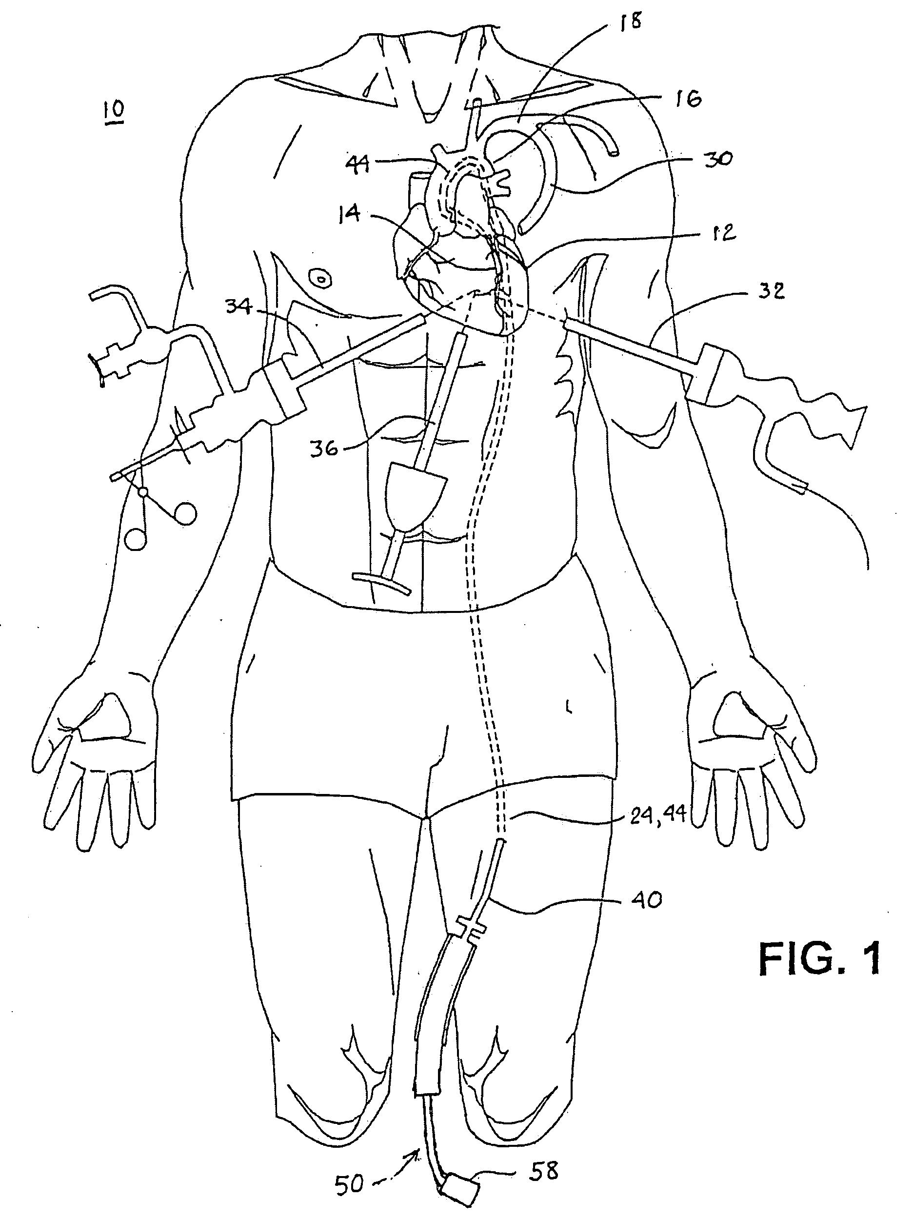
[0083]For example, while a preferred method of performing a coronary artery anastomosis in a thoracoscopic CABG procedure will be described below, it is to be understood that the principles of the present invention can be applied to a wide variety of surgical procedures, both conventional, open procedures, as well as minimally invasive procedures. The present invention is also of great use to facilitate other medical procedures where it is desirable to locate the distal end of a catheter or guidewire or the like within a lumen of a body vessel.

[0084]The initial stages of an artery-to-artery coronary bypass procedure in accordance with the present invention in which an end-to-side vascular anastomosis is to be established between the severed end of the left...


PUM


Abstract

Methods and apparatus employed to locate body vessels and occlusions in body vessels finding particular utility in cardiac surgery, particularly minimally invasive cardiac surgery to locate cardiac arteries and occlusions in cardiac arteries are disclosed. An elongated vessel lumen probe incorporating a lumen probe element at or near the elongated vessel lumen probe distal end is advanced into the vessel lumen. A vessel surface probe manipulated by the surgeon and having a surface probe element sensor is employed to detect the lumen probe element and to follow the progress of the vessel lumen probe element as it approaches and is advanced through or is blocked by an occlusion. In the location of a coronary artery, the surface probe element sensor is moved about against the epicardium over the suspected location of the artery of interest until a surface probe element sensor of the present invention at the surface probe distal end interacts with the lumen probe element of the vessel lumen probe.

Description

RELATED APPLICATION[0001]This application claims priority under 35 U.S.C. § 120 to U.S. patent application Ser. No. 10 / 278,531, filed Oct. 23, 2002, which application is incorporated by reference herein in its entirety.FIELD OF THE INVENTION[0002]The present invention pertains to methods and apparatus employed to locate body vessels and occlusions in body vessels finding particular utility in cardiac surgery, particularly minimally invasive cardiac surgery to locate cardiac arteries and occlusions in cardiac arteries.BACKGROUND OF THE INVENTION[0003]Diseases of the cardiovascular system affect millions of people each year and are a leading cause of death throughout the world. The cost to society from such diseases is enormous both in terms of the number of lives lost as well as in terms of the costs associated with treating patients through traditional surgical techniques. A particularly prevalent form of cardiovascular disease is coronary artery disease (CAD), which is caused by at...

Claims


Application Information

Patent Timeline
Patent Type & Authority Applications(United States)
IPC IPC(8): A61B5/05A61B5/06A61B17/00A61B17/22A61B19/00
CPCA61B5/06A61B5/062A61B2017/00022A61B2019/461A61B2017/00252A61B2017/22001A61B2017/00243A61B2090/061
Inventor BONNER, MATHEW D.CLAGUE, CYNTHIA T.JAHNS, SCOTT E.KEOGH, JAMES R.
Owner MEDTRONIC INC
Why Eureka
Try Eureka