Controlled steering of a flexible needle

a flexible needle and controlled steering technology, applied in the direction of sensors, catheters, diagnostics, etc., can solve the problems of poor technique and needle placement, significant limitations of methods, and percutaneous needle insertion

Active Publication Date: 2009-06-11
TECHNION RES & DEV FOUND LTD
View PDF14 Cites 117 Cited by
  • Summary
  • Abstract
  • Description
  • Claims
  • Application Information

AI Technical Summary

Benefits of technology

[0008]The present invention seeks to provide a new, computer controlled robotic system, and associated method, for closed-loop steering of a flexible needle during insertion into soft-tissue, using imaging to determine the needle position. The control system calculates a needle tip trajectory that hits the desired target while avoiding en route obstacles, impingement on which may be potentially dangerous to the subject. The system then preferably utilizes an inverse kinematics algorithm, to calculate the maneuvers required of the needle base to cause the tip to follow the desired trajectory, such that the robot can perform controlled needle insertion.

Problems solved by technology

In general, complications of percutaneous needle insertion are due to poor technique and needle placement.
However, this method has significant limitations since as the needle penetrates the tissue, the tissue deforms and thus, even when working with straight rigid needles the needle might miss the target.
In some cases the problem remains that rigid needles lead to excessive, injurious pressure on tissues.
However, a major disadvantage to using thin flexible needles is that they are difficult to control.
They have non-minimum phase behavior and do not lend themselves to intuitive (human) control.
A limitation of this work is that due to the computation complexity, it does not allow for real-time simulation and control of the needle insertion.

Method used


Image

  • Controlled steering of a flexible needle
  • Controlled steering of a flexible needle
  • Controlled steering of a flexible needle

Examples


Embodiment Construction

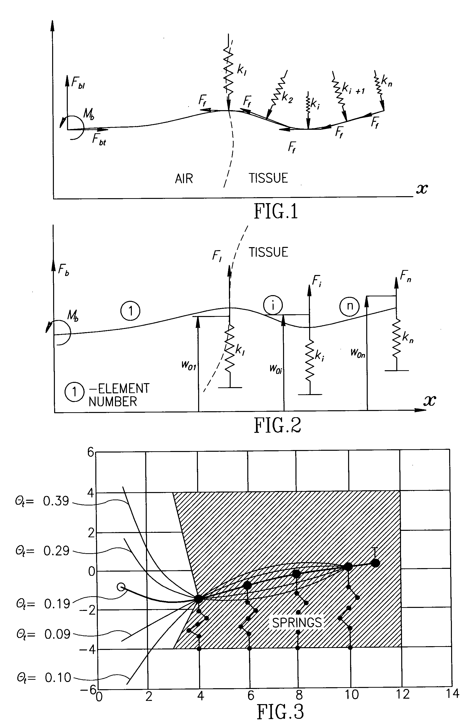
[0060]Reference is now made to FIG. 1, which illustrates schematically a model of the interaction of the tissue with the needle as represented by a series of distributed virtual springs, having coefficients k1, k2, . . . kn as first used in the above-mentioned MICCAI 2003 article by the present inventors. The tissue surface is denoted in FIG. 1 by the dashed line. The modeling of flexible needle movements is based on the assumption of quasistatic motion; the needle is in an equilibrium state at each step. It is known that needle deflection due to interactions with biologic soft tissue is nonlinear with strain. However, it is reasonable to assume a linear lateral force response for small displacements. Thus, the tissue forces on the needle are modeled as a combination of lateral virtual springs distributed along the needle curve plus friction forces Ff tangential to the needle. Since the tissue elastic modulus changes as a function of strain, the coefficients, k, of the virtual sprin...


PUM


Abstract

A robotic system for steering a flexible needle during insertion into soft-tissue using imaging to determine the needle position. The control system calculates a needle tip trajectory that hits the desired target while avoiding potentially dangerous obstacles en route. Using an inverse kinematics algorithm, the maneuvers required of the needle base to cause the tip to follow this trajectory are calculated, such that the robot can perform controlled needle insertion. The insertion of a flexible needle into a deformable tissue is modeled as a linear beam supported by virtual springs, where the stiffness coefficients of the springs varies along the needle. The forward and inverse kinematics of the needle are solved analytically, enabling both path planning and correction in real-time. The needle shape is detected by image processing performed on fluoroscopic images. The stiffness properties of the tissue are calculated from the measured shape of the needle.

Description

FIELD OF THE INVENTION[0001]The present invention relates to the field of percutaneous insertion of needles for therapeutic or diagnostic purposes, and especially to methods of guiding such needles to their target while avoiding sensitive organs en route.BACKGROUND OF THE INVENTION[0002]The trend of contemporary medicine is towards less invasive and more localized therapy. Many routine treatments employed in modern clinical practice involve percutaneous insertion of needles and catheters for biopsy and drug delivery. The aim of a needle insertion procedure is to place the tip of an appropriate needle safely and accurately in a lesion, organ or vessel. Examples of treatments requiring needle insertions include vaccinations, blood / fluid sampling, regional anesthesia, tissue biopsy, catheter insertion, cryogenic ablation, electrolytic ablation, brachytherapy, neurosurgery, deep brain stimulation and various minimally invasive surgeries.[0003]In general, complications of percutaneous ne...

Claims


Application Information

Patent Timeline
Patent Type & Authority Applications(United States)
IPC IPC(8): A61B19/00A61B5/05
CPCA61B17/3403A61B17/3478A61B19/22A61B19/2203A61B19/50A61B19/52A61B2019/5251A61B19/5244A61B2019/2226A61B2019/502A61B2019/507A61B2019/5238A61B19/5212A61B34/10A61B34/20A61B34/30A61B34/70A61B90/36A61B90/361A61B2034/102A61B2034/107A61B2034/2051A61B2034/304A61B2090/376
Inventor GLOZMAN, DANIELSHOHAM, MOSHE
Owner TECHNION RES & DEV FOUND LTD
Why Eureka
Try Eureka