
Photoimageable Nozzle Members and Methods Relating Thereto

a technology of photoimageable nozzles and nozzle parts, which is applied in the direction of recording apparatuses, instruments, and photosensible materials, can solve the problems of alignment problems, microfluid ejection heads are more expensive to manufacture, and speed and quality do not come without a price, so as to improve speed and quality, improve the quality of printers, and improve the effect of speed and quality

Active Publication Date: 2009-06-18
FUNAI ELECTRIC CO LTD
View PDF6 Cites 6 Cited by
  • Summary
  • Abstract
  • Description
  • Claims
  • Application Information

AI Technical Summary

Benefits of technology

This solution enables wafer-level processing, reduces manufacturing costs, improves adhesion and durability, and enhances the performance of micro-fluid ejection heads by simplifying the manufacturing process and eliminating alignment tolerances.

Problems solved by technology

However, the improvement in speed and quality does not come without a price.
The micro-fluid ejection heads are more costly to manufacture because of tighter alignment tolerances.
However, minor imperfections in the substrate or nozzle plate components of the ejection head or improper alignment of the parts has a significant impact on the performance of the ejection heads.
While the use of an imaged photoresist layer improves alignment of the flow features to the ejection actuators, there still exist alignment problems and difficulties associated with a nozzle plate attached to the thick film layer.
Misalignment between the ejection actuators and corresponding nozzles (e.g., holes) in a nozzle plate has a disadvantageous effect on the accuracy of fluid droplets ejected from the nozzles when the nozzles are formed in the nozzle plate before attaching the nozzle plate to the thick film layer.
However, developing the flow features in the thick film layer after applying the nozzle plate materials to the thick film layer requires difficult processing techniques.
Such relatively thick photoresist materials are too thick for use in providing a suitable photoimageable nozzle plate for a micro-fluid ejection head.
If the photoresist materials are screened down to an appropriate thickness, the resulting photoresist films becomes too brittle to handle and apply by a lamination process to the thick film layer.

Method used


Image

  • Photoimageable Nozzle Members and Methods Relating Thereto
  • Photoimageable Nozzle Members and Methods Relating Thereto
  • Photoimageable Nozzle Members and Methods Relating Thereto

Examples


Embodiment Construction

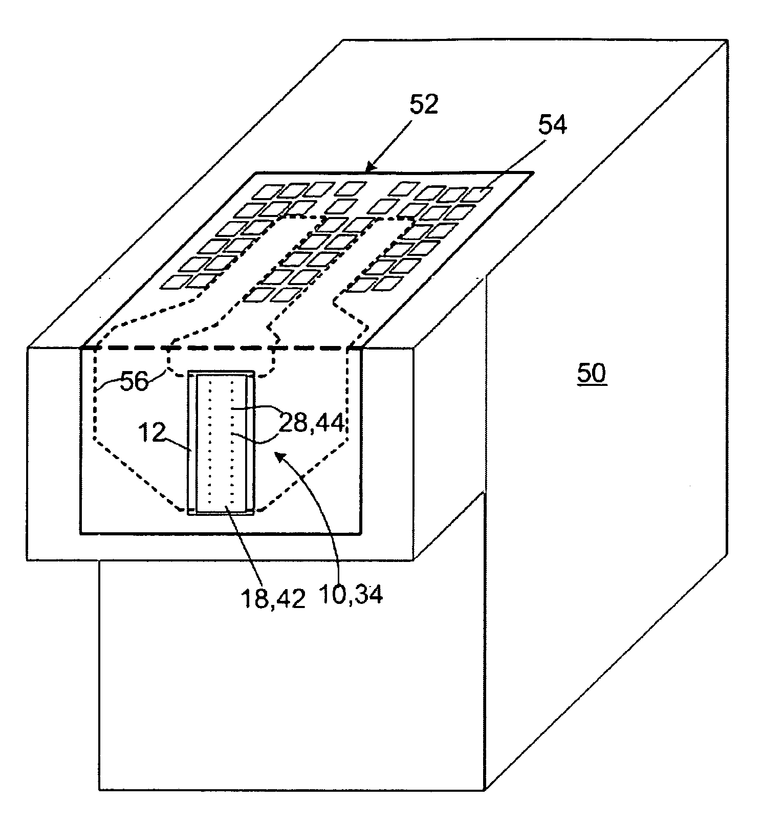
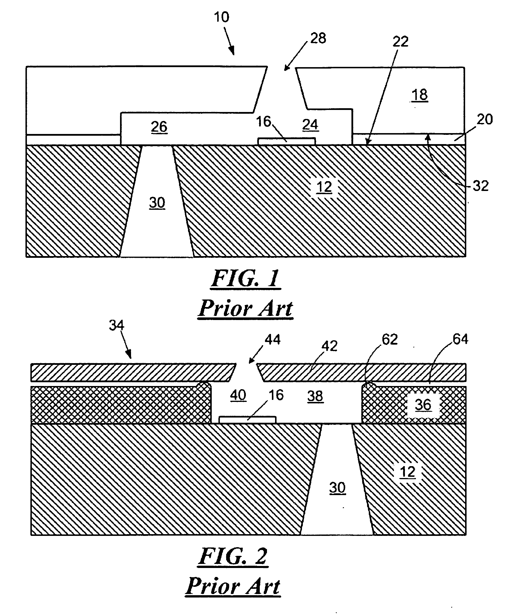
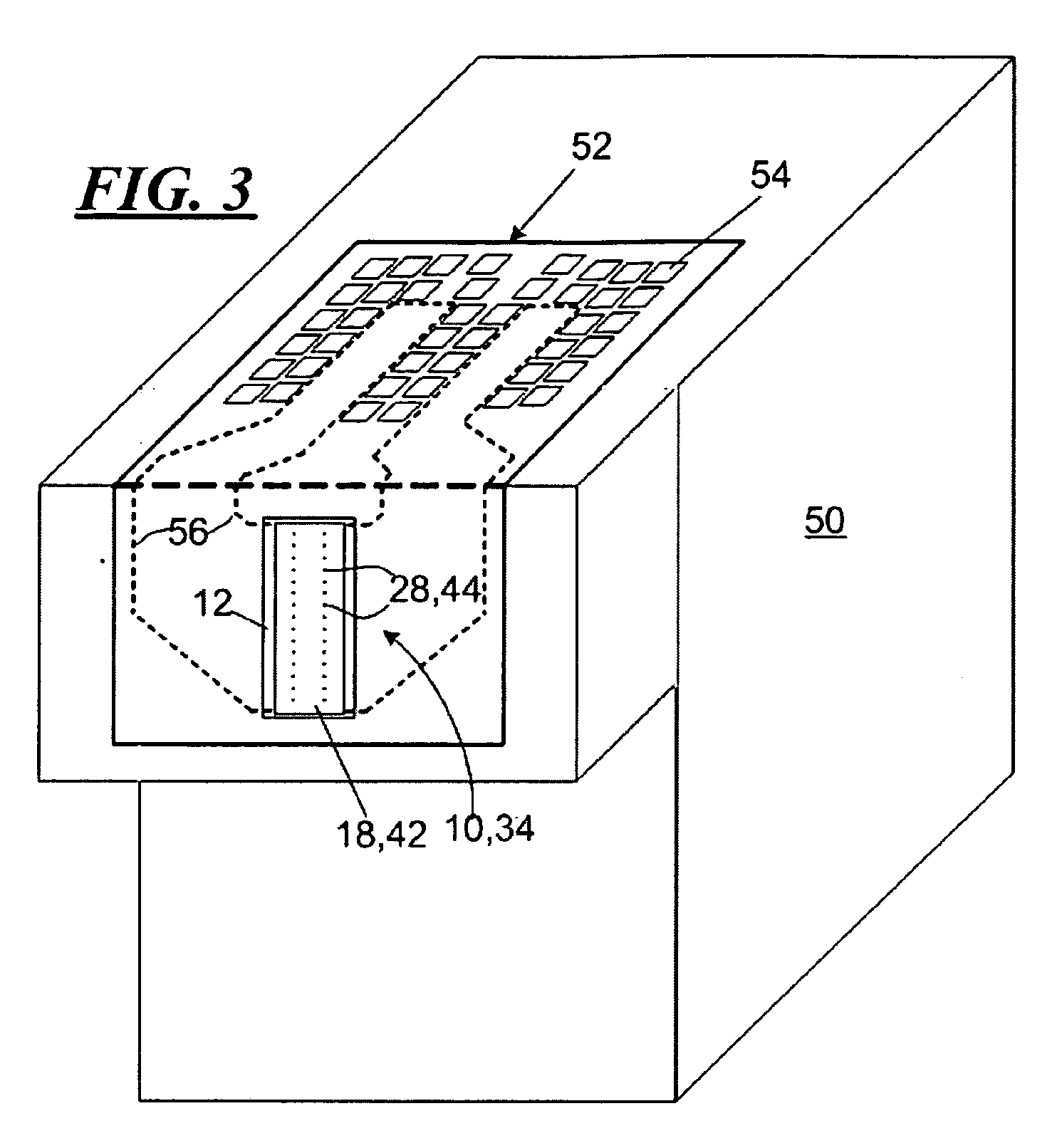
[0026]With reference to FIG. 1, there is shown, in partial cross-sectional view, a portion of a prior art micro-fluid ejection head 10. The micro-fluid ejection head 10 includes a semiconductor substrate 12 containing various insulative, conductive, resistive, and passivating layers providing a fluid ejector actuator 16.

[0027]In a prior art micro-fluid ejection head 10, a nozzle plate 18 is attached as by an adhesive 20 to a device surface 22 of the semiconductor substrate 12. In such micro-fluid ejection head 10, the nozzle plate 18 is made out of a laser ablated materials such as polyimide. The polyimide material is laser ablated to provide a fluid chamber 24 in fluid flow communication with a fluid supply channel 26. Upon activation of the ejector actuator, fluid is expelled through a nozzle 28 that is also laser ablated in the polyimide material of the nozzle plate 18. The fluid chamber 24 and fluid supply channel 26 are collectively referred to as “flow features.” A fluid feed ...


PUM

PropertyMeasurementUnit
thicknessaaaaaaaaaa
thicknessaaaaaaaaaa
thicknessaaaaaaaaaa

Abstract

Nozzle members, such as for a micro-fluid ejection head, micro-fluid ejection heads, and a method for making the same. One such nozzle member includes a negative photoresist composition derived from a first di-functional epoxy compound, a relatively high molecular weight polyhydroxy ether, a photoacid generator devoid of aryl sulfonium salts, an adhesion enhancer, and an aliphatic ketone solvent. The nozzle member has a thickness ranging from about 10 microns to about 30 microns.

Description

CROSS-REFERENCE TO RELATED APPLICATION[0001]Pursuant to 37 C.F.R. § 1.78, this application is a divisional and claims the benefit of the earlier filing date of application Ser. No. 11 / 361,732 filed Feb. 26, 2006 entitled “Photoimageable Nozzle Members and Methods Relating Thereto.”FIELD OF THE INVENTION[0002]The invention relates to improved photoimageable dry film formulations for use in making nozzle members, such as for micro-fluid ejection heads and to methods for attaching a nozzle member to a substrate for a micro-fluid ejection head having a thick film layer derived from a radiation curable resin formulation.BACKGROUND AND SUMMARY[0003]Micro-fluid ejection devices, such as ink jet printers continue to evolve as the technology for ink jet printing continues to improve to provide higher speed, higher quality printers. However, the improvement in speed and quality does not come without a price. The micro-fluid ejection heads are more costly to manufacture because of tighter alig...

Claims


Application Information

Patent Timeline
Patent Type & Authority Applications(United States)
IPC IPC(8): G03F7/20
CPCB41J2/1603B41J2/1645B41J2/1631B41J2/162
Inventor WEAVER, SEAN T.WELLS, RICH
Owner FUNAI ELECTRIC CO LTD
Learn More