Device and method for tacking plaque to blood vessel wall
a technology of plaque and blood vessel wall, which is applied in the field of atherosclerosis occlusive disease treatment, can solve the problems of uncontrolled plaque disruption, the lumen of the blood vessel at the site of treatment is usually somewhat larger, and the balloon angioplasty process is full dilatation to its intended size, so as to reduce the risk of recurrent stenosis, less scaffolding structure, and less body reaction
- Summary
- Abstract
- Description
- Claims
- Application Information
AI Technical Summary
Benefits of technology
Problems solved by technology
Method used
Image
Examples
third embodiment
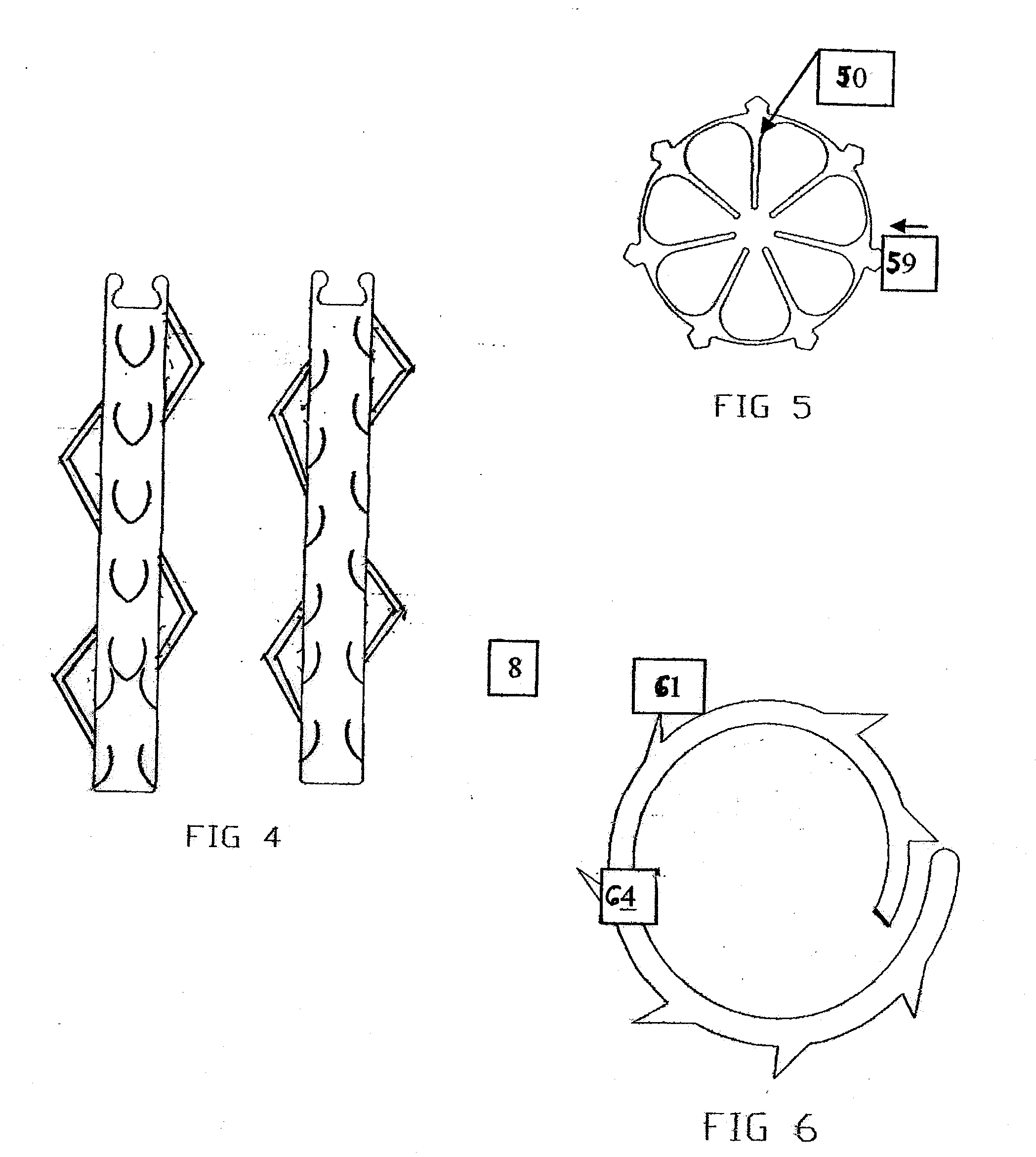
[0054]FIGS. 7A-7D show alternative shapes for FIG. 5 with a variety of different anchoring designs 72, 73, 78, 80. The fingers 76, 77 for bending the points flat for insertion are included with any of the designs. When the fingers are removed after pre-loading, and the flexible ring tack has been deployed, the inner area 74, 75 within the annular ring 79, 82 is left unobstructed.
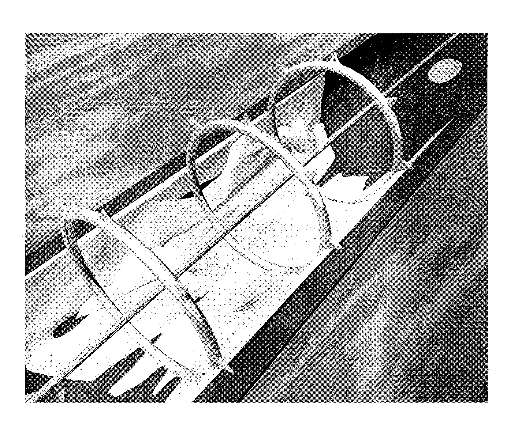
[0055]Referring to FIG. 6, a fourth preferred embodiment of the plaque tack device is formed in a coil shape 64 with ends unjoined and with barbs or points 61 on its outer periphery. The ends are pulled longitudinally in opposite directions to flatten the annular band to a spiral shape extending linearly so that it can be carried around or inside the length of a tubular sheath into the blood vessel held in place by a retainer element. At the desired position in the blood vessel, the retainer element is released to allow the tack to expand back to its full-diameter annular shape against the plaque.
[0056]FIGS....
fifth embodiment
[0059]the plaque tack in the form of a wire mesh tack is illustrated in FIGS. 19A-D, and its manner of deployment in FIGS. 20 and 21. In FIG. 19A, the wire mesh tack is shown in end view having an annular band 100a formed of interleaved wire mesh, and outer points or barbs 100b. The wire mesh tack is made of thin metal wire which is looped and interleaved in a mesh that is welded, soldered, looped and / or linked together into the desired mesh shape. FIG. 19B shows the wire mesh tack in side view with barbs projecting from the annular band 100a. The barbs on its outward surface will contact and embed into the wall of the blood vessel. FIG. 19C shows the wire mesh tack at rest in its fully expanded state in perspective view, and FIG. 19D shows a section of the wire mesh tack in a detailed view. The intermeshed pattern formed by the wire mesh is specifically designed so that it can be compressed radially inward to a smaller-volume size for loading on a catheter delivery device to be ins...
PUM
 Abstract
Description
Claims
Application Information
 - R&D
- Intellectual Property
- Life Sciences
- Materials
- Tech Scout
- Unparalleled Data Quality
- Higher Quality Content
- 60% Fewer Hallucinations
Browse by: Latest US Patents, China's latest patents, Technical Efficacy Thesaurus, Application Domain, Technology Topic, Popular Technical Reports.
© 2025 PatSnap. All rights reserved.Legal|Privacy policy|Modern Slavery Act Transparency Statement|Sitemap|About US| Contact US: help@patsnap.com


