Apparatus of chemical vapor deposition with a showerhead regulating injection velocity of reactive gases postively and method thereof

a technology of reactive gas and apparatus, which is applied in the direction of chemical vapor deposition coating, coating, metallic material coating process, etc., can solve the problems of unwanted deposits flaking off into fine particles, contaminated substrates, and heterogeneous reactions on solid-state surfaces, so as to prevent contamination at the inside of the reactive gas confining means, suppress the diffusion of reactive gas backwardly, and increase the growth rate of films

Active Publication Date: 2009-07-02
KOREA INST OF IND TECH +1
View PDF69 Cites 113 Cited by
  • Summary
  • Abstract
  • Description
  • Claims
  • Application Information

AI Technical Summary

Benefits of technology

[0014]As described above the present invention has a function that each reactive gas passes through a showerhead independently, thereby preventing mixing of the reactive gases at inside of the showerhead. Moreover, the present invention has a function that a purge gas is injected from a bottom surface of the showerhead and forms a protective curtain beneath the bottom of the showerhead, thereby suppressing diffusion of the reactive gas backwardly. Moreover, the present invention has a function that the injection velocity of each reactive gas is positively regulated by controlling the amount of the injection support gas which is mixed to the reactive gas in the showerhead, thereby determining composition of the film growing on substrates easily. Furthermore, the present invention has a function that the temperature of showerhead is maintained at proper levels by mounting a cooling jacket which constitutes the lowest part of the showerhead, thereby unwanted film deposition caused by thermal decomposition of the reactive gases is suppressed at inside and bottom of the showerhead. In addition to this, if the present invention is applied to a CVD system together with a reactive gas confining means, the contamination at inside of the reactive gas confining means is prevented, and the film growth rate is increased by confining the reactive gas in the vicinity of the substrates.

Problems solved by technology

Unfortunately, if reactive gases whose decomposition temperature are substantially lower than 200° C. like metal-organic compounds are mixed in the reaction chamber, the mixture may cause homogeneous reactions in the gas phase leading to a generation of contaminant particles, or cause heterogeneous reactions on a solid-state surface such as a showerhead surface or a reaction chamber wall.
The unwanted deposits are eventually flaked off into fine particles due to a repeated thermal expansion and contraction and / or a lattice parameter mismatch between the surface materials and the deposits.
As a result of this, the film formed on the substrate may be contaminated and the productivity becomes deteriorated due to a shortened process management cycle time to remove the unwanted deposits.
When a highly integrated semiconductor is manufactured, contaminant particles may cause a pattern defect such as a short or disconnection between lines, and the size of the contaminant particle influencing yield is in proportion to the line width.
Therefore, as the line size becomes smaller, that is, as the density of the integration is increased, the size of particle influencing yield becomes smaller, whereby the number of contaminant particles to be permitted in the reaction chamber is more seriously limited.

Method used


Image

  • Apparatus of chemical vapor deposition with a showerhead regulating injection velocity of reactive gases postively and method thereof
  • Apparatus of chemical vapor deposition with a showerhead regulating injection velocity of reactive gases postively and method thereof
  • Apparatus of chemical vapor deposition with a showerhead regulating injection velocity of reactive gases postively and method thereof

Examples


example 1

[0044]FIG. 14 shows a first example that the showerhead 100 of the present invention is applied to a reactive gas confining means 900. Here, the reactive gas confining means 900 is spaced apart from the inner wall 7 and the ceiling of the reaction chamber 1 at a distance, surrounds the substrate 9 with a dome-like roof, touches the bottom 961 of the reaction chamber along its end, has a large number of fine holes formed thereon and an opening part formed at the central portion of the roof thereof on which the rim of the showerhead 100 is placed along the opening so that the bottom surface of the showerhead 100 and the substrate are in parallel to and facing each other. Details about the reactive gas confining means are incorporated in U.S. Pat. No. 7,156,921 by reference.

[0045]As shown in FIG. 14, two reactive gases, two injection support gases, and a first purge gas are delivered into the showerhead 100 through a reactive gas supply tubes 954A and 954B, injection support gas supply...

example 2

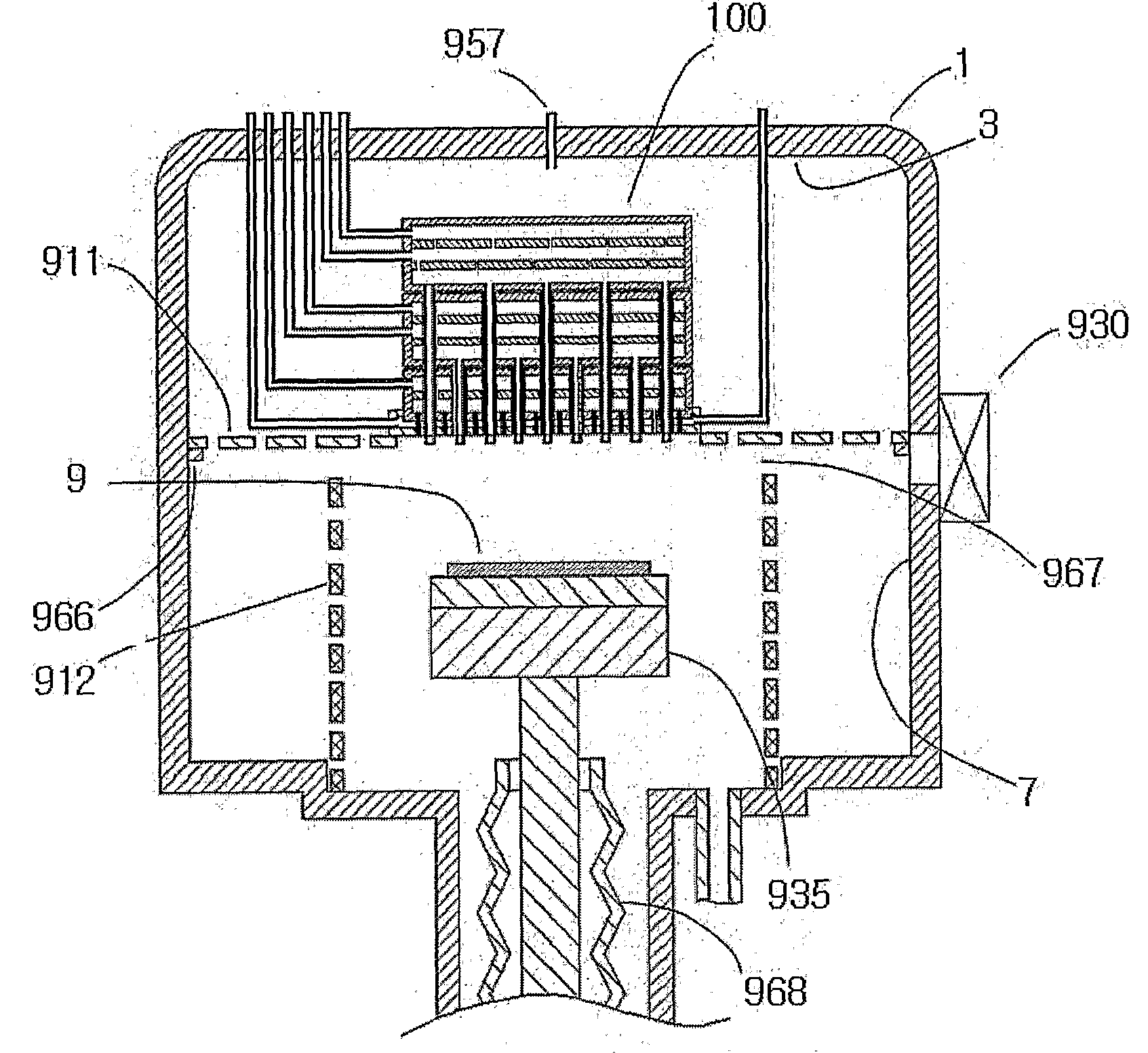
[0046]FIG. 15 shows a case that the showerhead 100 of the present invention is applied to a reactive gas confining means 900 of another type. Here, the reactive gas confining means 900 has a ceiling with a flat rim. The ceiling with a rim can be easily mounted on a device such as a protruded spot 966 in the reaction chamber 1. And a gap between the ceiling and the vertical wall of the reactive gas confining means could be easily formed to permit in and out of the substrate 9. As the gap 967 is opened by lowering the vertical wall 912 of the reactive gas confining means using a kind of lever (not shown) attached to the bellows 968 which is hermetically joined to the stage 935, in and out of the substrate 9 would be performed by inserting a robot arm (not shown) from a transfer chamber (not shown) to the reaction chamber 1 through a gate valve 930 and the gap 967 followed by raising and lowering of the stage 935.

[0047]While the present invention has been described with reference to th...


PUM

PropertyMeasurementUnit
diameteraaaaaaaaaa
diameteraaaaaaaaaa
inner diameteraaaaaaaaaa

Abstract

The present invention is related to an apparatus and a method for chemical vapor deposition (CVD) using a showerhead through which a reactive gas of at least one kind and a purge gas is injected over a substrate on which a film is growing. A plural number of reactive gas showerhead modules are laid on a purge gas showerhead module. Each reactive gas is injected from a bottom of the showerhead after flowing through the showerhead as separated, thereby preventing the reactive gases from causing homogeneous gas phase reactions and from generating unwanted particles at the inside of the showerhead. And purge gas is injected from the bottom surface of the showerhead by forming a protective curtain, thereby suppressing diffusion of the reactive gas injected backwardly. Each reactive gas is mixed with an injection support gas which is a kind of inert gas in a mixing zone at inside of the showerhead, where the injection velocity of each reactive gas is regulated positively by the amount of the injection support gas mixed. The present invention further includes an apparatus and a method, wherein the showerhead is cooled by a cooling jacket which keeps the temperature of the showerhead at proper levels to prevent both the condensation and the thermal decomposition of the reactive gas used.

Description

TECHNICAL FIELD[0001]The present invention relates to an apparatus and a method for chemical vapor deposition (CVD) with a showerhead which supplies a plural kind of reactive gases and a purge over a substrate to grow a film on the substrate uniformly in thickness and composition. Here, the present invention is associated with U.S. Pat. No. 7,156,921 (“Method and apparatus for chemical vapor deposition capable of preventing contamination and enhancing film growth rate”, filed on Oct. 9, 2002), the entire contents of which are hereby incorporated by reference.BACKGROUND ART[0002]In an apparatus for chemical vapor deposition (CVD), a reactive gas is introduced into a vacuum reaction chamber, flows through a showerhead, and reaches a susceptor or a substrate holder on which a substrate is located. The reactive gas causes chemical reaction on the substrate to form a desired film. As a means to provide energy necessary to induce chemical reactions on the substrate, a method of simply hea...

Claims


Application Information

Patent Timeline
Patent Type & Authority Applications(United States)
IPC IPC(8): C23C16/18
CPCC23C16/45565H01L21/67069C23C16/45574C23C16/45572C23C16/40C23C16/45514C23C16/45578
Inventor BYUN, CHUL SOOHAN, MAN CHEOL
Owner KOREA INST OF IND TECH
Why Eureka
Try Eureka