Heat resisting vacuum insulating material and heating device

a vacuum insulating material and heat-resisting technology, which is applied in the direction of heater elements, machines/engines, light and heating apparatus, etc., can solve the problems of large energy efficiency problems, piping resistance to exhaust gas becomes too great to continue vacuumizing, and the yield of dust to the semiconductor circuit substrate brings a drop in yield, so as to prevent the yield from being reduced, reduce the workload of hazardous maintenance work, and reduce the effect of sticking

Active Publication Date: 2009-07-23
PANASONIC CORP +1
View PDF1 Cites 15 Cited by
  • Summary
  • Abstract
  • Description
  • Claims
  • Application Information

AI Technical Summary

Benefits of technology

[0015]The present invention, attempted on the basis of those findings, is intended to provide a heat resisting vacuum insulator excelling in heat resistance and heat retaining property and a heating device which is enabled by the use of this material to prevent unused active chemical species from sticking to and accumulating on the inner walls of the bodies and / or exhaust pipes of various vacuum devices, thereby to solve dust-attributed problems in the bodies of such vacuum devices and the problem of clogging of the exhaust pipes, with the result that thinner exhaust pipes than conventional ones can be used and maintenance of the exhaust pipes is facilitated.
[0028]Therefore, the heating device in any of the ninth through fifteenth aspects, synergy between the heat resisting vacuum insulator and a specific electric heater having a resistance heating element and a heat resisting electric insulator can prevent unused chemical species in the vacuum device from sticking to the inner walls of the device body, and accordingly prevent the yield from being reduced by the sticking of such species onto the semiconductor substrate as dust. Also, it is possible to significantly restrain the sticking of unused chemical species contained in the gas discharged from the vacuum device to the inner wall of the exhaust pipe, and in particular the sticking of such chemical species can be securely prevented by heating with the electric heater the outer wall of the exhaust pipe to 140° C. or above, preferably to about 150° C.
[0029]For this reason, the maintenance workload requiring hazardous work can be alleviated by substantially reducing the frequency of exhaust pipe cleaning, which has been performed periodically with the vacuum device suspended in the conventional practice. As a result, the utilization rate of expensive semiconductor manufacturing apparatuses, in which such vacuum devices are used, can be enhanced.
[0030]Also, the elimination of the chemical species sticking to the inner wall of the exhaust pipe enables the bore of the exhaust pipe of the vacuum device, which conventionally is 150 to 200 mm in diameter, to be reduced to between 10 and 50 mm, which is a sufficient diameter for essential exhaust, with the result that the capacity of the vacuum pump for exhaust discharge can be reduced and accordingly the discharge power requirement can be reduced to between ½ and 1 / 10 of that in use of a conventional exhaust pipe.
[0031]Furthermore, as this heating device occupies a small volume after it is fitted to the exhaust pipe of the vacuum device, when it is applied to a vacuum device as a semiconductor manufacturing apparatus for instance, the exhaust pipe of the apparatus laid underneath the clean room floor would require less adjustment with the arrangement of other installations, the execution or undertaking of both or entire working would be facilitated.

Problems solved by technology

In various vacuum devices conventionally used for semiconductor manufacturing such as sputtering devices, CVD (Chemical Vapor Deposition) devices and dry etching devices, high temperature active chemical species generated through reactions in such a device stick to the low temperature pipe walls of the vacuum device without being captured onto the semiconductor circuit substrate, then they become dust and scattered, and sticking of this dust to the semiconductor circuit substrate brings a drop in yield.
When the effective bore of the exhaust pipe narrows in this way, the piping resistance to the exhaust gas becomes too great to continue vacuumizing, and the operation of the vacuum device has to be suspended to scrape off the chemical species having clogged the exhaust pipe.
However, this way of widening the bore of the exhaust pipe makes the capacity of the exhaust pipe greater than that of the vacuum device body, and discharging through the exhaust pipe requires enlarged exhaust capacity of the vacuum pump, entailing a big problem in energy efficiency.
The chemical species accumulating in the exhaust pipe, which are highly reactive with oxygen, would cause an abrupt combustion when coming into contact with air, often causing a fire.
This causes a serious problem of hazardous work that has to be done by a number of human works.
Also, this clogging of the exhaust pipe has been a major bottleneck to the further development of the semiconductor industry as it not only brings down the utilization rate of the equipment but also requires a great number of cleaning labor.
It therefore is made correspondingly more difficult to feed the heating device-equipped exhaust pipe which is greater in sectional area than a conventional pipe through the limited space under the floor on which the vacuum device is installed.
However, this vacuum insulating material, intended for use in electrical household appliances such as cooking heaters or warmth keeping heaters, is only about 200 mm×300 mm in size.
Vapor deposition is applicable to the formation of such a small film, but a vacuum insulating material of 1 m or more in length or one for use in industrial equipment or piping cannot be formed by vapor deposition.
The reason is that vapor deposition devices are hardly applicable for use with very large sheets of 1 m or more in length, and moreover it is difficult to fill the spaces in so large sheets uniformly with silica powder.

Method used


Image

  • Heat resisting vacuum insulating material and heating device
  • Heat resisting vacuum insulating material and heating device
  • Heat resisting vacuum insulating material and heating device

Examples


first embodiment

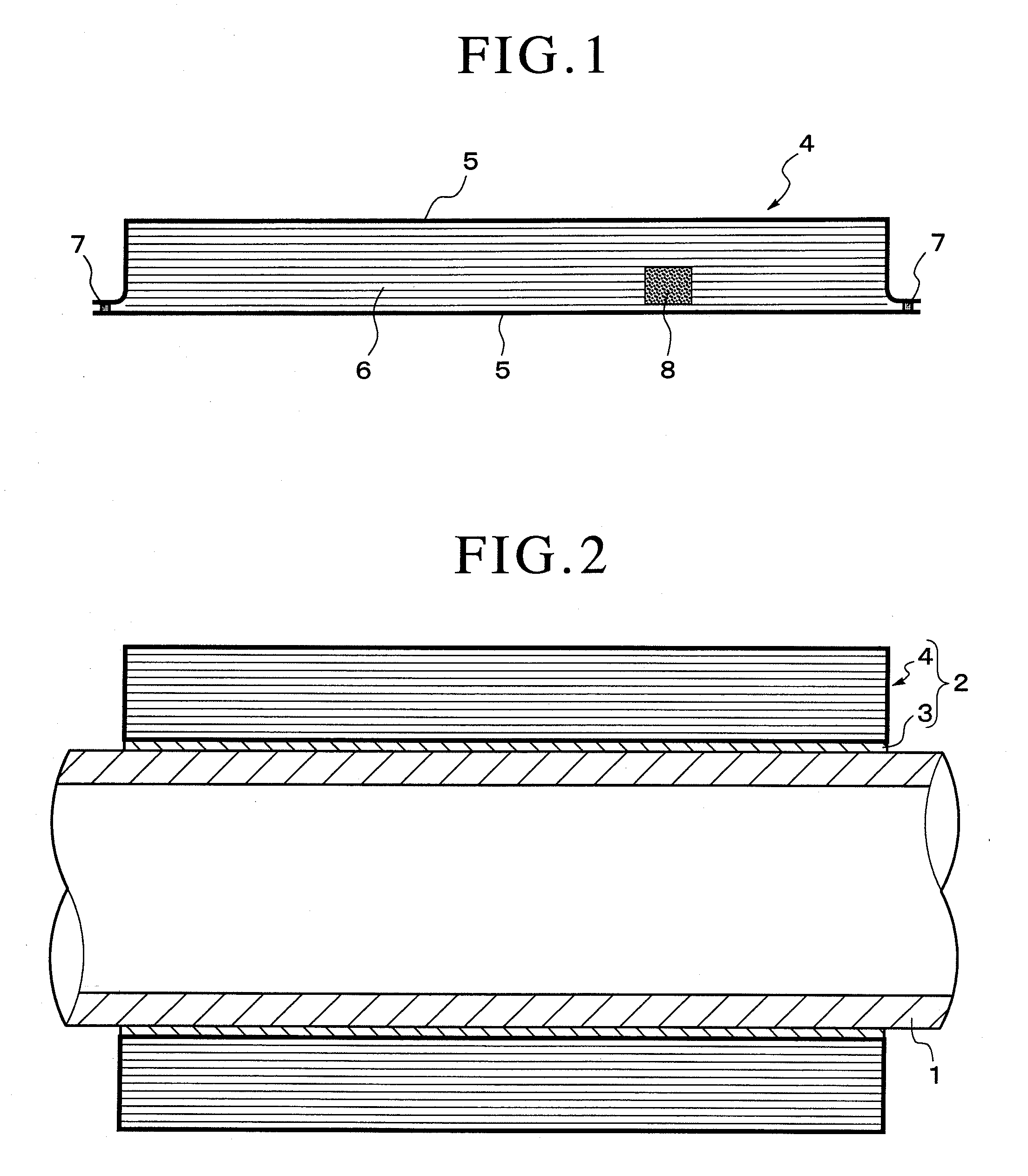
[0048]FIG. 1 and FIG. 2 show the heating device in a first embodiment, in which the heating device 2 is substantially composed of an electric heater 3 arranged along the outer wall of the exhaust pipe 1 and a heat resisting vacuum insulator 4 covering the outer periphery of the electric heater 3.

[0049]The electric heater 3 further comprises a resistance heating element and a heat resisting electric insulator made up of an organic macromolecular material and covering the resistance heating element.

[0050]The resistance heating element is a wire-shaped or sheet-shaped item made of a metallic or carbon-based material having a high electric resistance, which preferably may be 0.5 to 100Ω. Where a wire-shaped item is used as the resistance heating element, it is preferable that its thickness be between 50 and 1000 μm, and where a sheet-shaped item is used, it is preferable that its thickness be between 10 μm and 100 μm.

[0051]More specifically, suitable carbon-based resistance heating elem...

second embodiment

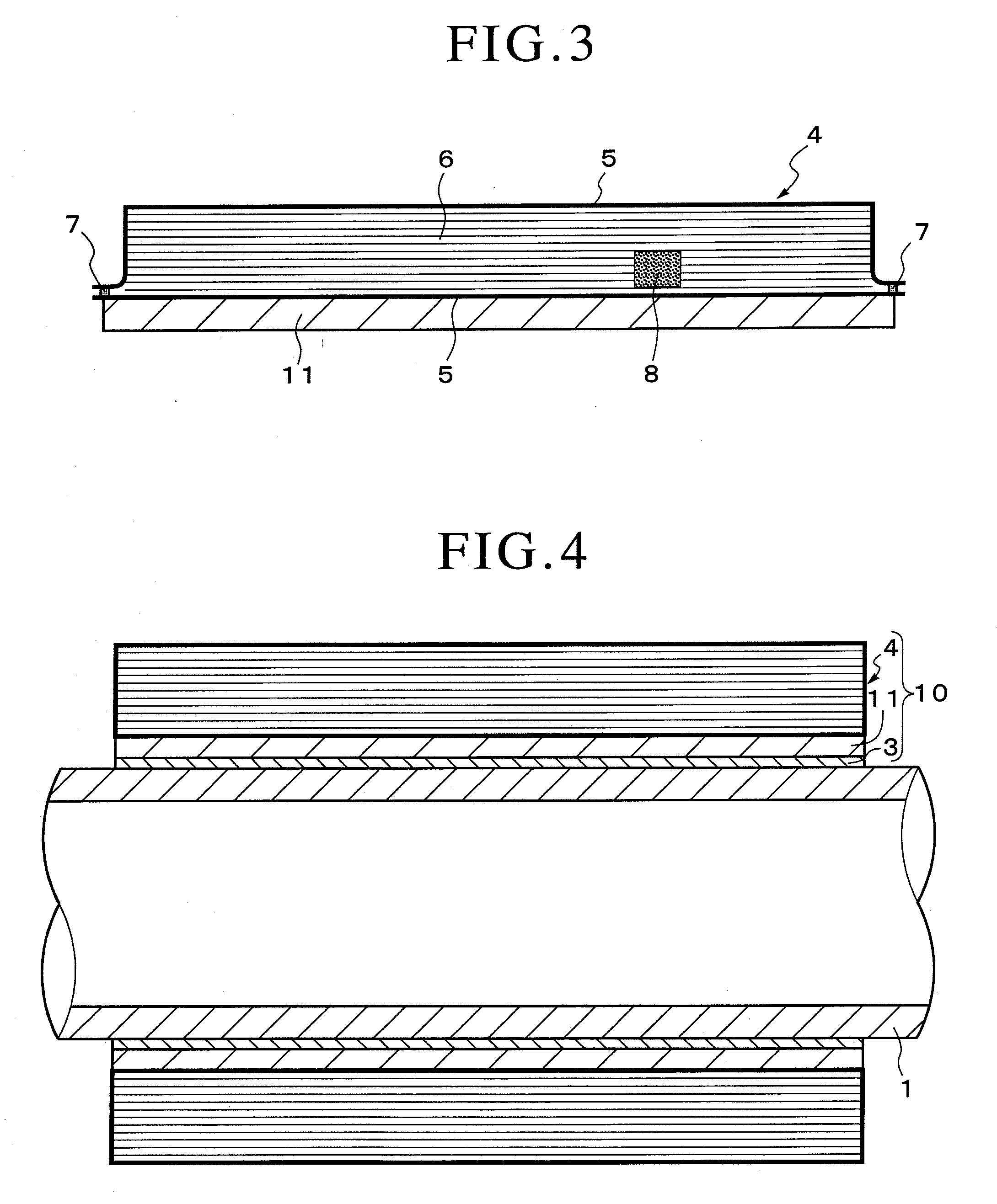
[0059]FIG. 3 through FIG. 5 show a second embodiment of the invention and a modified version of the same. The same constituent parts as those in FIG. 1 and FIG. 2 are assigned respectively the same reference signs, and their description is simplified.

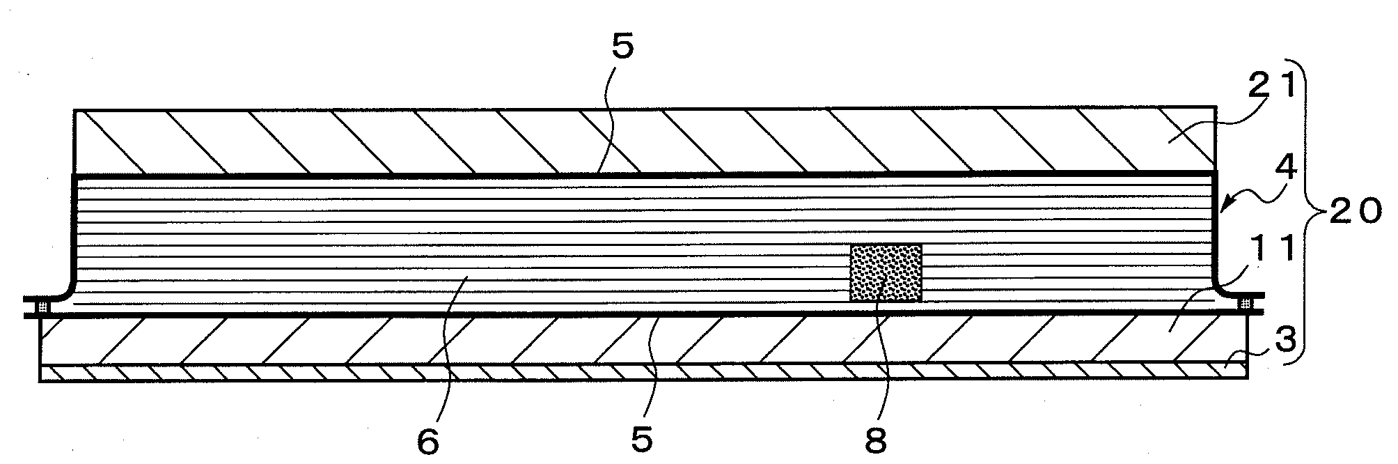
[0060]As shown in FIG. 3 and FIG. 4, the heating device 10 has an insulating material 11, made up of an inorganic material, disposed between the heating device 2 and the exhaust pipe 1 in the first embodiment, while a heating device 20 shown in FIG. 5 has an insulating material 21, made up of an organic or inorganic material, wound around the outer periphery of the heating device 10 of FIGS. 3 and 4.

[0061]Inorganic materials usable for the insulating materials 11 and 21 include cloth knit of non-boron glass, such as soda glass, fibers or quartz fibers and calcium silicate boards. The reason why boron-containing glass fibers, such as borosilicate glass processed into fibers, are not used is to avoid the problem of diffusion of boron comp...

example 1

[0066]To assess the heating performances of the heating devices according to the invention and the insulating performances of the heat resisting vacuum insulators used therein, the following performance tests were carried out.

(1) Heat Resisting Vacuum Insulators

[0067]The heat resisting vacuum insulators were prepared in the following way.

[0068]For the metal sheet to constitute the covering for keeping the vacuum within each heat resisting vacuum insulator, a metallic foil basically having no gas transmissivity, such as an aluminum foil or a stainless steel foil was used. When an aluminum foil was used in particular, a plastic protective sheet was stuck to the atmosphere-facing surface of this foil to prevent it from being broken. On the vacuum side, it had an adhesive layer made up of an adhesive resin to apply sealing to maintain the vacuum.

[0069]For the filling material to be contained in the metal sheet, a molded item formed by heat-resistant fibrous, ball-shaped or otherwise sha...


PUM


Abstract

A heating device which can prevent unused active chemical species from attaching to the bodies of various vacuum devices or depositing on the inner wall of their exhaust pipes to thereby be able to make the size of exhaust pipes smaller than before and make the exhaust pipe maintenance easier. The heating device comprises a heat resisting vacuum insulator (4) wound around the outer periphery of an electric heater (3) disposed along the outer wall of an exhaust pipe (1), wherein the electric heater (3) has a resistance heating element and a heat resisting electric insulator covering this resistance heating element, and the heat resisting vacuum insulator (4) comprises a hollow platy covering material air-tightly sealed thereinside by a metal seat (5) having a heat resisting temperature of at least 100° C., and a fibrous or granular filling material (6) filled in the hollow portion of this covering material and having a heat resisting temperature of at least 100° C., the inside of the covering material being kept vacuum.

Description

TECHNICAL FIELD[0001]The present invention relates to a heat resisting vacuum insulator that can be suitably fitted to the body and / or the exhaust pipe of various vacuum devices such as vacuum devices for semiconductor circuit formation, and a heating device using the same.BACKGROUND ART[0002]In various vacuum devices conventionally used for semiconductor manufacturing such as sputtering devices, CVD (Chemical Vapor Deposition) devices and dry etching devices, high temperature active chemical species generated through reactions in such a device stick to the low temperature pipe walls of the vacuum device without being captured onto the semiconductor circuit substrate, then they become dust and scattered, and sticking of this dust to the semiconductor circuit substrate brings a drop in yield. The dust is discharged from the vacuum device, then cooled by the inner wall of its exhaust pipe and sticks and accumulates thereon, causing a phenomenon that the effective bore of the exhaust p...

Claims


Application Information

Patent Timeline
Patent Type & Authority Applications(United States)
IPC IPC(8): H05B3/02D02G3/00
CPCC23C14/22C23C14/56C23C16/4412F16L53/008Y10T428/2933F16L59/065H01L21/67103F01N13/08F01N13/146F16L58/00F16L53/38
Inventor OHMI, TADAHIROSHIRAI, YASUYUKIKOBAYASHI, SADAOWAKAYAMA, YOSHIHIDEUEKADO, KAZUTAKA
Owner PANASONIC CORP
Why Eureka
Try Eureka