Merocyanine dye and photoelectric conversion device

Active Publication Date: 2009-07-23
FUJIFILM CORP
View PDF0 Cites 12 Cited by
  • Summary
  • Abstract
  • Description
  • Claims
  • Application Information

AI Technical Summary

Benefits of technology

[0010]An object of the invention is to provide a merocyanine dye having a novel structure and to provide a photoelectric conversion device which uses such a merocyanine dye and thereby achieves high sensitivity, distinctive spectral sensitivity characteristics, a low dark current and a fast response speed.

Problems solved by technology

However, those devices have problems that the aperture rates thereof decrease as they are made finer, and they require additional devices such as lenses.
Although various suggestions have been made for improvements of those devices, drawbacks including low efficiency of light utilization still remain.
923 (1984) are cited as the cases where merocyanine dyes are used in photoelectric conversion devices, the photoelectric conversion powers attained therein are not sufficient.

Method used


Image

  • Merocyanine dye and photoelectric conversion device
  • Merocyanine dye and photoelectric conversion device
  • Merocyanine dye and photoelectric conversion device

Examples


example 1

[0097]To 3.2 g of 50% NaH, a mixed solution of 10 g of naphthalene-2,3-dicarboxylic acid dimethyl ester and 15 ml of ethyl acetate was added dropwise, and heated under reflux for 4 hours. After cooling to room temperature, the resulting reaction solution was passed through a filter, and the filtrate was added to a solution prepared by mixing 20 ml of hydrochloric acid and 200 ml of water and warming them to 80° C., and then stirred for 10 minutes. After cooling to room temperature, the filtration and subsequent drying were carried out. Thus, 4.1 g of Intermediate 1 was obtained.

[0098]Acetonitrile in an amount of 40 ml was added to a 2.0 g portion of Intermediate 1 and 2.2 g of N,N′-diphenylformamidine, and heated under reflux for 5 hours. After cooling to room temperature, the resulting reaction solution was filtered to give 2.4 g of Intermediate 2.

[0099]A 0.6 g portion of Intermediate 2, 0.8 g of 1,2,3,3-tetramethylindolium iodide, 0.4 ml of piperidine and 20 ml of acetonitrile wer...

example 2

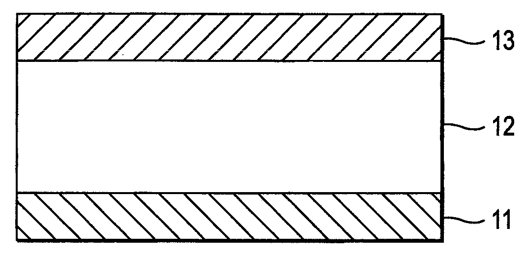
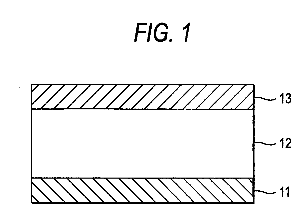
[0105]On a silicon substrate, 30 nm-thick amorphous ITO film was formed by a sputtering method to make a lower electrode. On the lower electrode thus made, a photoelectric conversion layer was formed by evaporating 100 nm-thick film of Compound A represented by the following chemical formula onto the lower electrode by vacuum heating and then evaporating Compound 1 film having a thickness of about 100 nm onto the Compound A film by vacuum heating. On the photoelectric conversion layer thus formed, aluminum was formed into film by a vacuum heating evaporation method to make an upper electrode. Thus, a photoelectric conversion device 1 was prepared. By replacing Compound 1 with Compound 2, Compound 3, Compound 8 and Comparative Compound 1 (produced by HAYASHIBARA BIOCHEMICAL LABS., INC.: λmax 520 nm, molar absorption coefficient 91,100 l / mol / cm), respectively, photoelectric conversion devices 2, 3 and 4 and a photoelectric conversion device for comparison were prepared.
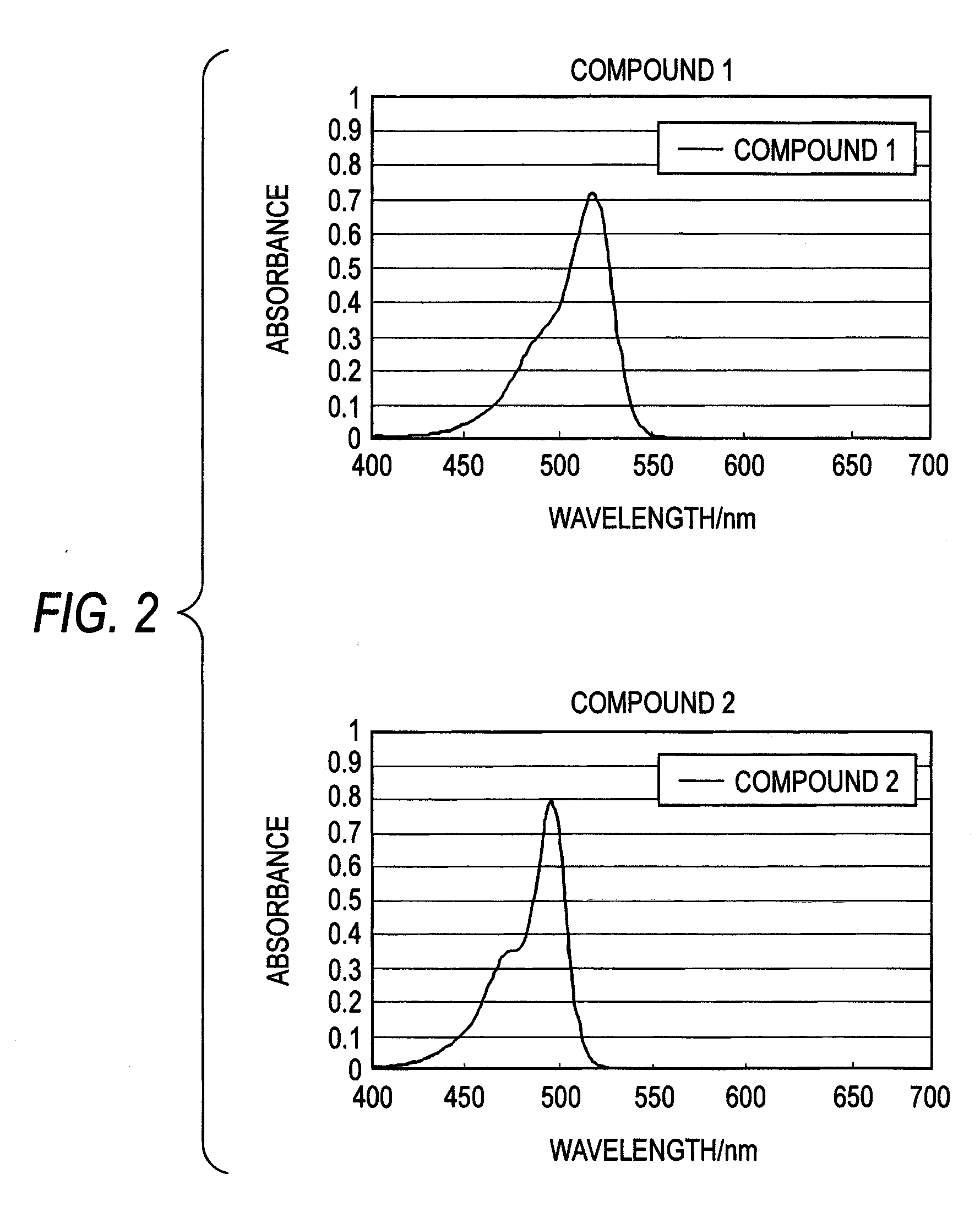
[0106]A chlorof...


PUM

PropertyMeasurementUnit
Fluorescence quantum yieldaaaaaaaaaa

Abstract

A merocyanine dye is provided. The merocyanine dye is represented by formula (1).In the formula (1), A1 represents a divalent atomic group, n represents an integer of 1 to 3, A2 and A3 each independently represent an aromatic hydrocarbon ring or a heterocyclic ring having 3 to 18 carbon atoms, and R11 and R12 each independently represent a hydrogen atom, an alkyl group having 1 to 18 carbon atoms, an aryl group having 6 to 18 carbon atoms, or a heterocyclic group having 3 to 18 carbon atoms.

Description

[0001]This application is based on and claims priority under 35 U.S.C. §119 from Japanese Patent Application No. 2008-009436 filed Jan. 18, 2008, the entire disclosure of which is herein incorporated by reference.BACKGROUND OF THE INVENTION[0002]1. Field of the Invention[0003]The present invention relates to a merocyanine dye and a photoelectric conversion device including a pair of electrodes and a photoelectric conversion section which is provided between the pair of electrodes and includes an organic photoelectric conversion layer.[0004]2. Description of Related Art[0005]Merocyanine dyes have been used for a wide range of applications because of their structural diversity and color tones. In particular, merocyanine dyes are useful as light absorption materials since they have highly selective absorption spectra and highly intense absorption spectra, and those having a wide variety of structures have been proposed in the field of silver-salt photography which utilizes their sensit...

Claims


Application Information

Patent Timeline
IPC IPC(8): H01L31/00C07D209/12C07D263/56C23C14/34G01J1/44C07D277/64
CPCC09B23/105H01L51/424H01L51/0064H01L51/0059H10K85/652H10K85/631H10K30/20H10K30/81
Inventor NOMURA, KIMIATSUSHEN, RUISUZUKI, HIDEYUKI
Owner FUJIFILM CORP
Why Eureka
Try Eureka