
Combustion-Assisted Substrate Deposition Method For Producing Carbon Nanosubstances

a carbon nanotube and substrate technology, applied in the direction of catalyst activation/preparation, physical/chemical process catalysts, metal/metal-oxide/metal-hydroxide catalysts, etc., can solve the problems of limiting the commercial success of products incorporating such materials, high cost of producing pure and uniform samples of cnts using currently available methods, and inability to produce pure cnts using this protocol

Inactive Publication Date: 2009-07-30
NANODYNAMICS INC
View PDF0 Cites 63 Cited by
  • Summary
  • Abstract
  • Description
  • Claims
  • Application Information

AI Technical Summary

Benefits of technology

[0011]The solid support may consist of any heat-resistant material having suitable mechanical strength to serve as a support for the harvesting layer; suitable materials include but are not limited to ceramics, glasses, and metals.
[0012]The harvesting layer is disposed on the surface of the solid support. It comprises one or more catalysts capable of inducing the formation of carbon nanotubes from a hot carbon-containing gas, and further comprises one or more refractory alkali- or acid-soluble metal salts, oxides or hydroxides. The harvesting layer is preferably soluble in an acid or alkali harvesting reagent that does not dissolve the solid support.
[0013]Suitable catalysts include but are not limited to transition metals, and salts, oxides, hydroxides, or other compounds or complexes thereof, for example those known in the art to be useful in making carbon nanotubes by the CVD and carbon arc processes.
[0014]The carbon-containing fuel is in gaseous form when incorporated into the combustible gas mixture, but may be derived from one or more gaseous, liquid, or solid carbon-containing substance...

Problems solved by technology

Although the potential for CNTs is tremendous, the cost of producing pure and uniform samples of CNTs using currently available methods is high, significantly limiting the commercial success of products incorporating such materials.
However, the CNTs produced using this protocol are not pure and contain a mixture of other carbon species, including amorphous and graphitic carbon particles.
Purification of the CNTs is difficult, and the final yield of CNTs is low.
The laser-ablation technology applies laser pulses, such as from a Nd:YAG laser, to ablate a target of graphite-metal composite in an inert gas atmosphere maintained at a high temperature, generally between 800-1600° C. However, the cost of CNTs produced using this method is also high.
The technology may be suitable for CNT synthesis on a laboratory scale, but it is not suitable for the large-scale production of CNTs required for commercial applications.
In addition to the downstream harvesting and purification issues, the CVD methods are energy intensive, and because the processes are constrained by the confines of an electrically heated vacuum furnace the method is not amenable to continuous operation or commercial-scale production.
CNTs may be formed on catalytic surfaces that favor the formation of nanotubes, but the collection of the nanotubes, especially from high-surface-area substrates designed to produce useful yields, remains difficult and is not amenable to automated large-scale production.

Method used


Image

  • Combustion-Assisted Substrate Deposition Method For Producing Carbon Nanosubstances
  • Combustion-Assisted Substrate Deposition Method For Producing Carbon Nanosubstances
  • Combustion-Assisted Substrate Deposition Method For Producing Carbon Nanosubstances

Examples


example 1

Laboratory Scale Synthesis

[0076]A titanium sheet having a thickness of 0.1 mm was formed into a cylinder having a diameter of 50 mm and a height of 15 mm. The cylinder was immersed in a 40 wt % aqueous solution of lithium silicate for about 1 minute, taken out, and dried at 120° C. for 1 hour, to form a lithium silicate film on the substrate.

[0077]The coated substrate was then immersed in a 5% by weight aqueous nickel nitrate solution for about 10 minutes, taken out, dried 120° C., and annealed at 600° C. for about 1 hour to generate a catalyst-bearing harvesting layer on the titanium support.

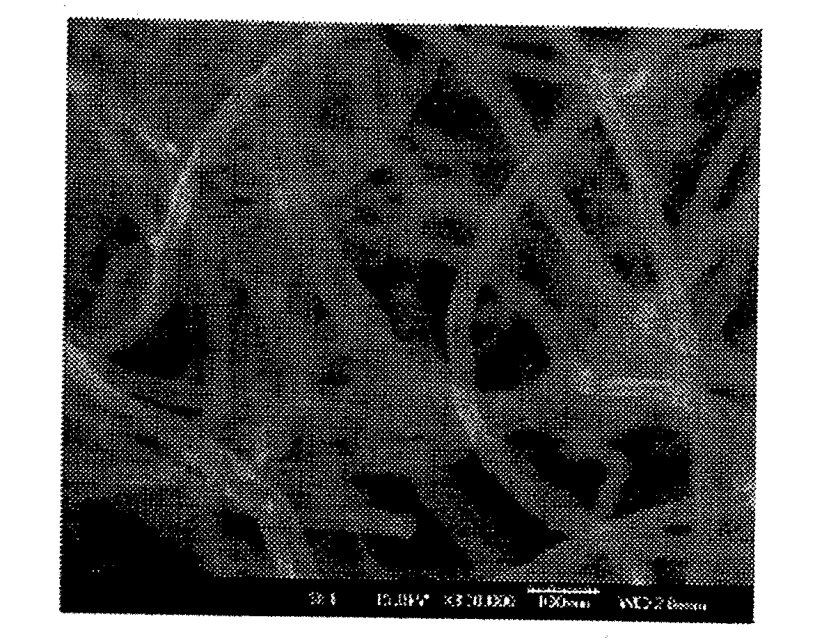
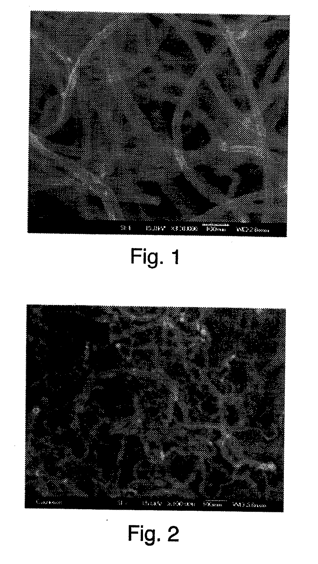
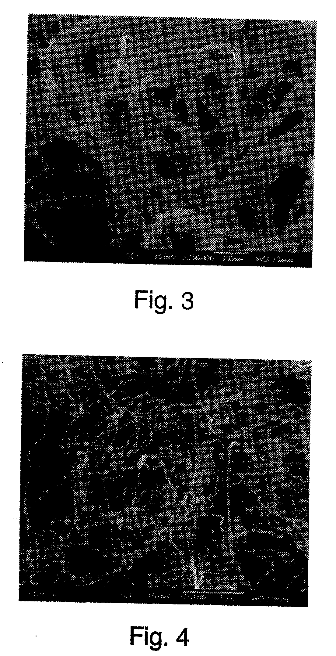
[0078]A premixed combustible gas composition consisting of ethylene and air was introduced into a burner, and this was ignited to generate a flame. The coated titanium cylinder was inserted and left in contact with the flame for 12 minutes. A black substance was produced on the substrate surface. Observation of the black substance with a scanning electron microscope revealed that it consisted e...

example 2

Pilot Scale Combustion System

[0080]Primary system components included a burner, a mounting plate, an electrical / control panel, a computer control station, gas supply tanks and automatic switch-over feed manifolds, a gas control panel, and a water cooling system. The burner and the mounting plate were housed in a 1 meter×1.3 meter exhausted section of the system.

[0081]The system included a computer control station, which was a standard PC running control and data acquisition / logging software (LabView™ 7, National Instruments Inc.) Gas flow was controlled by mass flow controllers and a dedicated control processor that was integrated into the LabView™ software. Automatic switch-over feed manifolds allowed continuous operation by sensing and switching from empty to full gas supply tanks, and empty tanks could be changed without interrupting the operation. Electrical controls ensured safe operation by interlocking several key variables, including hood pressure (exhaust flow), internal te...


PUM

PropertyMeasurementUnit
Temperatureaaaaaaaaaa
Solubility (mass)aaaaaaaaaa

Abstract

The present invention provides a combustion-based method and apparatus for producing and isolating carbon nanotubes. The nanotubes are formed when hot combustion gases are contacted with a catalytic surface, which is readily separated from the catalyst support and subsequently dissolved. The process is suitable for large-scale manufacture of carbon nanotubes.

Description

FIELD OF THE INVENTION[0001]The present invention relates generally to methods for producing carbon nanotubes. More particularly, it relates to the production of carbon nanotubes by a combustion process.BACKGROUND OF THE INVENTION[0002]Carbon nanotubes (“CNTs”) are widely sought for a variety of applications, including gas storage, absorption, intercalation media, catalyst supports, composite reinforcing materials, electrostatic charge dissipation, electrical conduction, and electromagnetic field shielding. Their advantage lies in both their structure and shape. They have a high aspect ratio and are extremely strong. The atomic level structure is akin to that of graphite; hence the useful electrical, thermal, and mechanical properties. When used as a component of composite materials, the one-dimensional morphology of CNTs permits the use of much lower mass loadings (˜1 / 10), compared to traditional additives such as carbon black, to realize a given increase in performance.[0003]Altho...

Claims


Application Information

Patent Timeline
IPC IPC(8): C23C4/04C23C16/01
CPCB01J23/28B01J23/745B01J23/755B01J23/78B01J23/881B01J23/882B01J23/8892B01J37/0225B01J37/0242B82Y30/00B82Y40/00C01B31/0226C01B31/0233C01B31/026C01B32/16C01B32/162C01B32/17
Inventor DUFAUX, DOUGLAS P.VANDER WAL, RANDYTANI, MASATOGOTO, TOSHIKI
Owner NANODYNAMICS INC
Learn More