Blanket sleeve and cylinder and method of making same

Inactive Publication Date: 2009-08-06
ROSSINI SPA
View PDF21 Cites 10 Cited by
  • Summary
  • Abstract
  • Description
  • Claims
  • Application Information

AI Technical Summary

Benefits of technology

[0022]An object of the present invention is therefore to provide a blanket cylinder and / or blanket sleeve having superior physical and mechanical characteristics than known cylinders and / or sleeves such as to offer higher wear resistance, better reboundability, and greater resistance to creases in the surface and hence prolong the useful life of the product. The blanket sleeve should be able to be removably coupled to the rotary member or support (mandrel) of the offset printing machine to form a portion of the blanket cylinder.
[0023]Still another principal object is to provide a blanket sleeve having a single polyurethane layer that is so consistent in regards to compressibility and surface tension that the sleeve does not need to be individually categorized like current blanket sleeves.
[0024]A further object is to provide a blanket sleeve of the stated type having a lower cost than known sleeves for known blanket cylinders.
[0025]A still further object of the invention is to provide a method whereby a blanket sleeve of the stated type can be produced in a shorter time than conventional sleeves.
[0026]A yet further object of the invention is to provide a method whereby a consistent blanket sleeve of the stated type can be produced regardless of ambient conditions and personnel available during production.
[0037]The result is a blanket sleeve that employs only one layer that desirably is composed of polyurethane containing evenly dispersed microspheres, which taken together occupy from about 0.6 percent by weight to about 4.4 percent by weight of the single, solid polyurethane layer, and that functions to provide adequate compressibility as found in conventional blanket sleeves and adequate incompressibility as required in conventional blanket sleeves and without any reinforcing layer. The single, solid polyurethane layer extends over the inner cylindrical body and has a density that desirably is between about 0.6 kg / dm3 and about 0.8 kg / dm3 and desirably is about 0.7 kg / dm3. The exterior surface (printing surface) of the single, solid polyurethane layer of the blanket sleeve desirably has a hardness of between about 50° Shore A and about 75° Shore A, and desirably between about 55° Shore A and about 65° Shore A, and desirably between about 58° Shore A and about 62° Shore A, and desirably is about 60° Shore A. The finished outer diameter of the single, solid polyurethane layer of the blanket sleeve has a tolerance of plus 0.02 mm and minus 0.01 mm. The total indicated runout (TIR, indicative of the degree to which the surface is out of round) of the finished outer surface of the single, solid polyurethane layer of the blanket sleeve is a maximum of 0.02 mm. Though the finished exterior surface of the single, solid polyurethane layer of the finished sleeve has tiny pores where the microspheres have released from the surface, as long as the weight of microspheres per 100 grams of polyol in the precursor material is kept within the critical range of not less than about one gram and not greater than about six grams, then the surface tension of the exterior surface of the finished blanket sleeve is conducive to releasing the ink to the substrate when the sleeve is in use on the printing machine.

Problems solved by technology

Over time, the ink, which can be acetate-based or alcohol-based, and the solvents tend to degrade the materials forming the blanket cylinder.
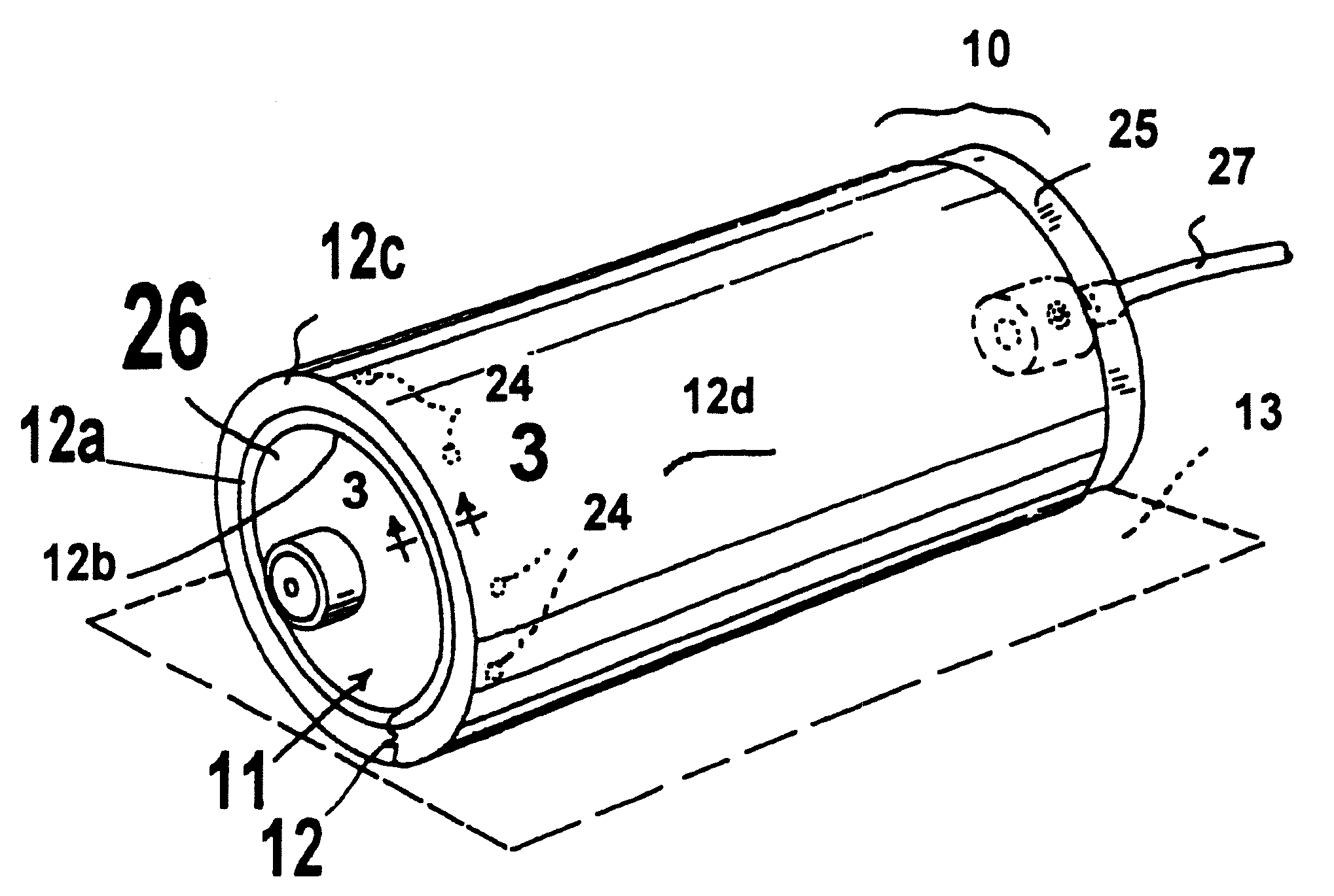
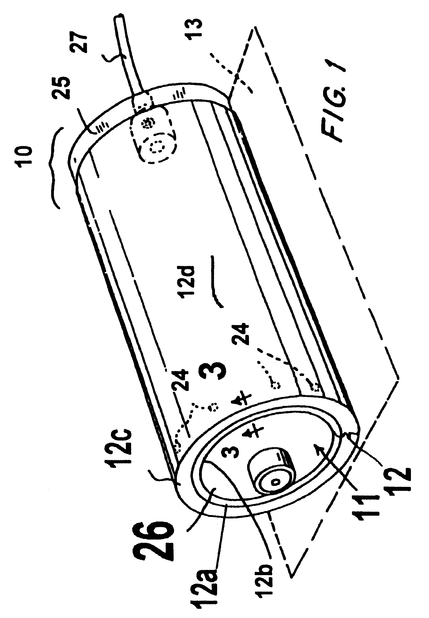
The use of this type of blanket cylinder gives rise to various problems, which for the most part arise due to the asymmetry of the slot in the outer surface of the rotating cylinder during operation of the printing machine.
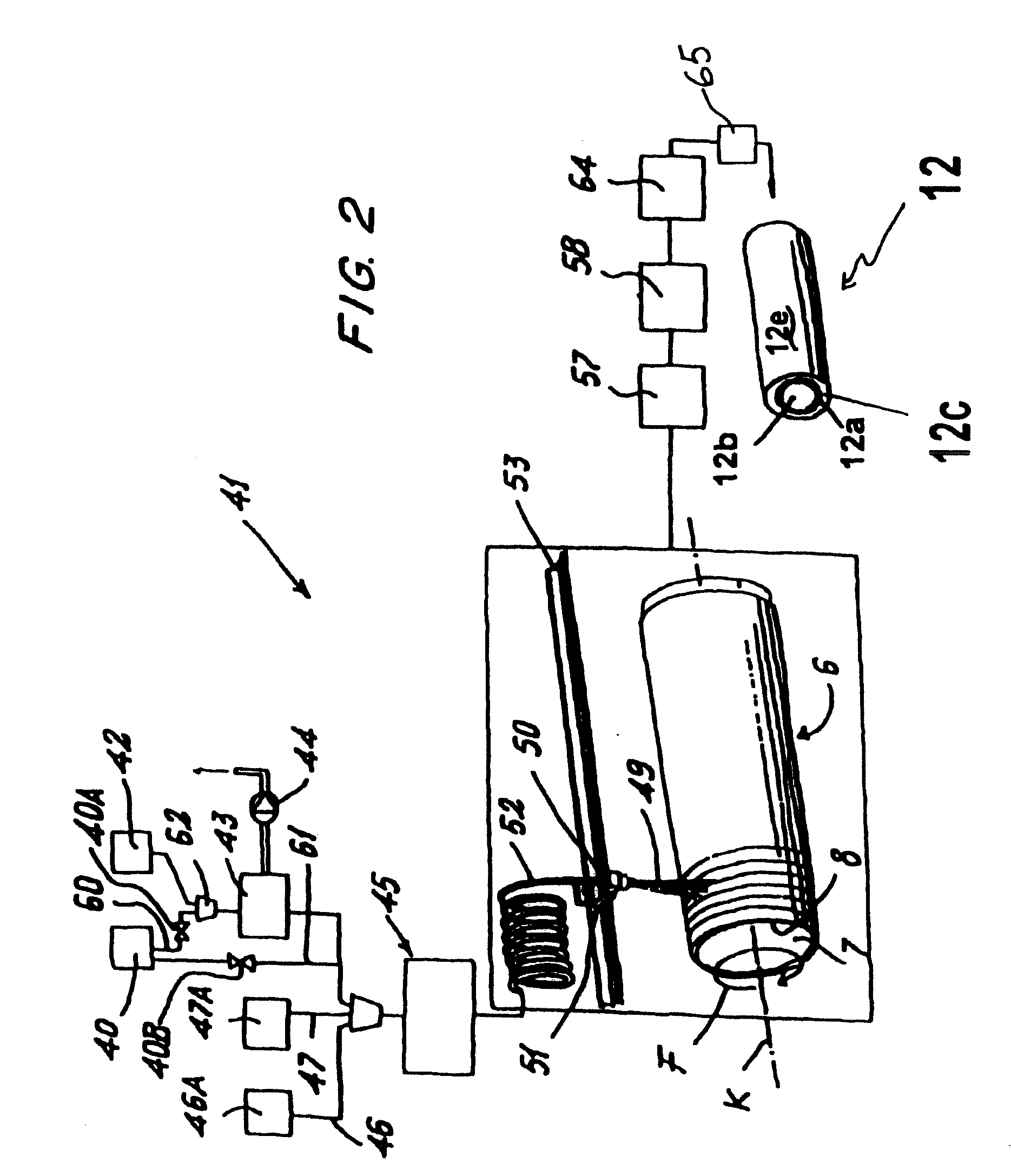
Then, in a very time consuming process that requires considerable operator skill, the nitrile rubber solution with the microspheres is applied to the surface of the inner cylinder (core) by a knife coating technology or ring coating technology for example to build up a precursor layer of about one millimeter in radial thickness.
However, because nitrile rubber does not adhere well to nickel surfaces, when the core is formed of nickel, an adhesive preparation must be provided.
However, the required operator involvement and manipulation steps in the production process required to fabricate the known blanket sleeve prevent significant automation of this fabrication process.
The low level of automation adversely affects the consistency of the sleeve that can be produced.
Indeed, the rampant inconsistency of the blanket sleeves has led many end users of the sleeves to test newly acquired sleeves and grade them A, B or C according to the degree of compressibility and assign them accordingly for various types of printing jobs.
However, the consistency of the compressible layer obtainable in the known rubber blanket sleeves is limited by the high degree of operator involvement and judgment during the fabrication process as well as by the unpredictable ambient conditions under which different sleeves are made for the same end-user.
Moreover, residual solvent in the compressible layer will continue to create voids in the compressible layer and thus changes the compressibility of the overall sleeve over time.
Thus, while a known rubber blanket sleeve may be delivered to the end-user with an acceptable compressibility, the compressibility of that sleeve may change enough over time to become outside the acceptable range.
Additionally, the aforesaid known blanket cylinder presents an outer layer of natural rubber or elastomeric material with inferior physical and mechanical characteristics, equivalent to those of rubber.
The outer layer has poor mechanical strength, at least partly because of these characteristics of natural rubber.
Consequently, the outer layer undergoes considerable wear during use.
This wear is caused by the action on this outer layer of the blanket sleeve by the metal plate of the plate cylinder or by the edges of the substrate being printed, or by poor resistance to the wash solvents used in the printing process.
A fold or other thickness variation in the substrate can irreversibly damage the surface of the outer layer and render the entire cylinder useless.
Once the original thickness of this outer printing layer is diminished, the blanket sleeve becomes incapable of transferring the inked data to the substrate with the desired resolution of the printed image.
This is particularly a problem in presses that print on both sides of the substrate and thus have a blanket cylinder on each side of the substrate, thus potentially doubling the problem as a bad image on one side of the substrate renders the entire substrate useless.
Furthermore, when the sleeve has a thin nickel core, the sleeve can become irreversibly damaged because the thin nickel core tends to kink during mounting and dismounting of the sleeve onto the rotary mandrel of the offset printing machine.
These factors combine to curtail the “useful life” or duration of a blanket sleeve of the aforesaid known type.
This curtailment presents obvious drawbacks from an economical viewpoint, especially in the cost of employing an offset printing machine that requires a plurality of blanket cylinders.

Method used


Image

  • Blanket sleeve and cylinder and method of making same
  • Blanket sleeve and cylinder and method of making same
  • Blanket sleeve and cylinder and method of making same

Examples


Embodiment Construction

[0048]Reference now will be made in detail to at least the presently preferred embodiments of the invention, one or more examples of which being set forth below. Each example is provided by way of explanation of the invention, not limitation of the invention. In fact, it will be apparent to those skilled in the art that various modifications and variations can be made in the present invention without departing from the scope or spirit of the invention. For instance, features illustrated or described as part of one embodiment, can be used on another embodiment to yield a still further embodiment. Thus, it is intended that the present invention cover such modifications and variations and their equivalents.

[0049]With reference to FIG. 1, a blanket cylinder for an offset printing machine is indicated overall by the numeral 10 and comprises a rotary support or mandrel 11 over which a layered sleeve 12 can be drawn. The mandrel / sleeve system can be either of two types. In one type, the in...


PUM


Abstract

A sleeve is provided to be drawn over a rotary support in order to define a blanket cylinder of an indirect or offset printing machine in which the blanket cylinder cooperates with a lithographic plate cylinder from which the sleeve receives the data to be printed onto a substrate which moves between the blanket cylinder and a pressure cylinder. The sleeve comprises an inner cylindrical portion configured to be drawn over the aforesaid rotary support. The outer surface of the inner cylindrical portion is covered by a single layer structure that cooperates directly with the lithographic plate and with the substrate to be printed. The single layer structure is composed at least partly of polyurethane material and cells occupying no less than about 0.6 percent by weight and no more than about 4.4 percent by weight and uniformly dispersed throughout the single layer. The single layer is formed of a precursor that is deposited by ribbon technology onto the outer surface of the inner cylindrical portion. The precursor includes two components. The first component includes polyol and microspheres wherein the microspheres constitute between about 1 percent by weight of the first component and about 6 percent by weight of the first component. The second component includes a curing agent for the polyol such that the weight ratio of the first component to the second component is in the range of about 100:38 to about 100:60.

Description

RELATED APPLICATIONS[0001]Benefit is hereby claimed to provisional patent application Ser. No. 61-026,021, filed on Feb. 4, 2008.BACKGROUND OF THE INVENTION[0002]The present invention relates to a sleeve for an indirect or offset printing machine and in particular to a sleeve to be carried on an offset blanket cylinder as well as to methods for making such sleeves.[0003]Offset printing machines or lithographic rotary printing machines with indirect printing are known, and examples are schematically represented in FIGS. 1 of U.S. Pat. Nos. 5,440,981 and 5,429,048, which patents are hereby incorporated herein in their entirety for all purposes by this reference. It is known that an offset machine or a lithographic rotary machine with indirect printing mainly comprises three rigid cylinders, usually made of steel. A first cylinder carries lithographic plates that, after being disposed into contact with inking rollers and wetting rollers, carry ink on some portions of the plates and an ...

Claims


Application Information

Patent Timeline
IPC IPC(8): B41N1/00
CPCB41N10/02B41N10/04B41N2210/14B41N2210/04B41N2210/02
Inventor ROSSINI, FELICE
Owner ROSSINI SPA
Why Eureka
Try Eureka