Rigid Amines

a technology of amines and amines, applied in the field of amine monomers, can solve the problems of poor performance poor performance of green and red emitters, and host may quench phosphor emission, so as to avoid the possibility of phase separation in blends, improve the lifetime of blue emissive materials, and improve the effect of polymer lifetim

Active Publication Date: 2009-08-20
CDT OXFORD +1
View PDF4 Cites 9 Cited by
  • Summary
  • Abstract
  • Description
  • Claims
  • Application Information

AI Technical Summary

Benefits of technology

[0013]Another approach is development of novel blue electroluminescent materials. For example, WO 00 / 55927, which is a development of WO 99 / 48160, discloses a blue electroluminescent polymer of formula (a):
[0014]wherein w+x+y=1, w≧0.5, 0≦x+y≦0.5 and n≧2.
[0015]In essence, the separate polymers disclosed in WO 99 / 48160 are combined into a single molecule. The F8 repeat unit is provided for the purpose of electron injection; the TFB unit is provided for the purpose of hole transport; and the PFB repeat unit is provided as the emissive unit. The combination of units into a single polymer may be preferable to a blend. For example, intramolecular charge transport may be preferable to intermolecular charge transport. Potential difficulties of phase separation in blends is also avoided.
[0016]WO 02 / 92723 and WO02 / 92724 disclose replacement of some of the F8 repeat units in the polymer illustrated above with 9,9-diarylfluorene repeat units, in particular diphenylfluorene (DPF) repeat units which has surprisingly been found to improve lifetime of the polymer.
[0017]WO 99 / 54385 and EP 1229063 disclose copolymers of fluorenes and PFB-type triarylamine repeat units. EP 1229063 discloses a copolymer of F8: TFB in a 70:30 ratio.
[0018]Although there has been much improvement in the lifetime of blue emissive materials there is always a desire to develop new blue emissive materials to further improve lifetime of the polymer.

Problems solved by technology

One drawback with existing polymer OLED displays relevant to this development is the relatively short lifetime of blue emissive materials known to date (by “lifetime” is meant the time for the brightness of the OLED to halve at constant current when operated under DC drive).
However, the advantage of selecting a cathode that improves blue lifetime may be offset by disadvantageous effects of the cathode on performance of red and green materials.
The present inventors have found that this cathode is particularly efficacious with respect to the blue emissive material but which shows poor performance with respect to green and, especially, red emitters.
A problem with known host-phosphor systems is that the host may quench emission from the phosphor.
As with phosphorescent systems, a problem with known host-fluorescent emitter systems is that the host may quench emission from the fluorescent emitter.
Another factor affecting the performance of opto-electonic devices is morphology of the films which make up the device.
Another problem with known devices results from charge migration past the emitting regions.
Accordingly, it is sometimes useful to provide charge-blocking materials.

Method used


Image

  • Rigid Amines
  • Rigid Amines
  • Rigid Amines

Examples


example 1

Monomer Example 1

[0127]Monomer 1 according to the invention, which is shown below, was synthesised according to Scheme 1:

[0128]Monomer 1 was synthesised in a four stage process as set out below.

Stage 1

[0129]

[0130]Phenyl hydrazine hydrochloride (30 g, 0.28 mol), tert-butyl cyclohexanone (42.79 g, 0.28 mol) and acetic acid (600 mL) were added to a round bottom flask, equipped with a nitrogen line and condenser. The reagents were stirred at room temperature for 30 mins and then warmed to 30° C. After 20 mins, the heating was increased to 35° C. and held at this temperature. After 30 mins, the heating was increased to 40° C. for a further 6 hours and then warmed to 70° C. overnight. The reaction mixture was allowed to cool to room temperature and then toluene was added. The organic phase was washed with water, NaHCO3 and finally water. The solvent was evaporated and the product recrystallized from hexane. Yielding 24.29 g (˜55% yield) of desired material.

Stage 2

[0131]

[0132]A 2 L flask e...

polymer example 1

[0151]A copolymer (Polymer l) having 65% F8, 30% DPF, and 5% Monomer 1 was formed by Suzuki polymerisation according to the method described in WO 00 / 53656.

[0152]The HOMO and LUMO of Polymer 1 were measured using cyclic voltametery:

[0153]HOMO level is very deep (similar to F8): 5.52 eV

[0154]LUMO level is shallow (similar to F8): 2.13 eV

[0155]The similarity to F8 suggests that both measured HOMO and LUMO levels are for F8 rather than the Monomer 1.

polymer example 2

[0156]An AB copolymer of 2,5-dioctylbenzene and the repeat unit derived from Monomer 1 (Polymer 2) was prepared by Suzuki polymerisation according to the method described in WO 00 / 53656 and the reaction scheme set out below, to give a polymer having a weight average molecular weight (Mw) of 57000 Daltons:

Device Example (Fluorescent Device)

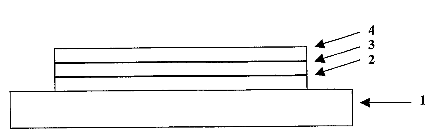
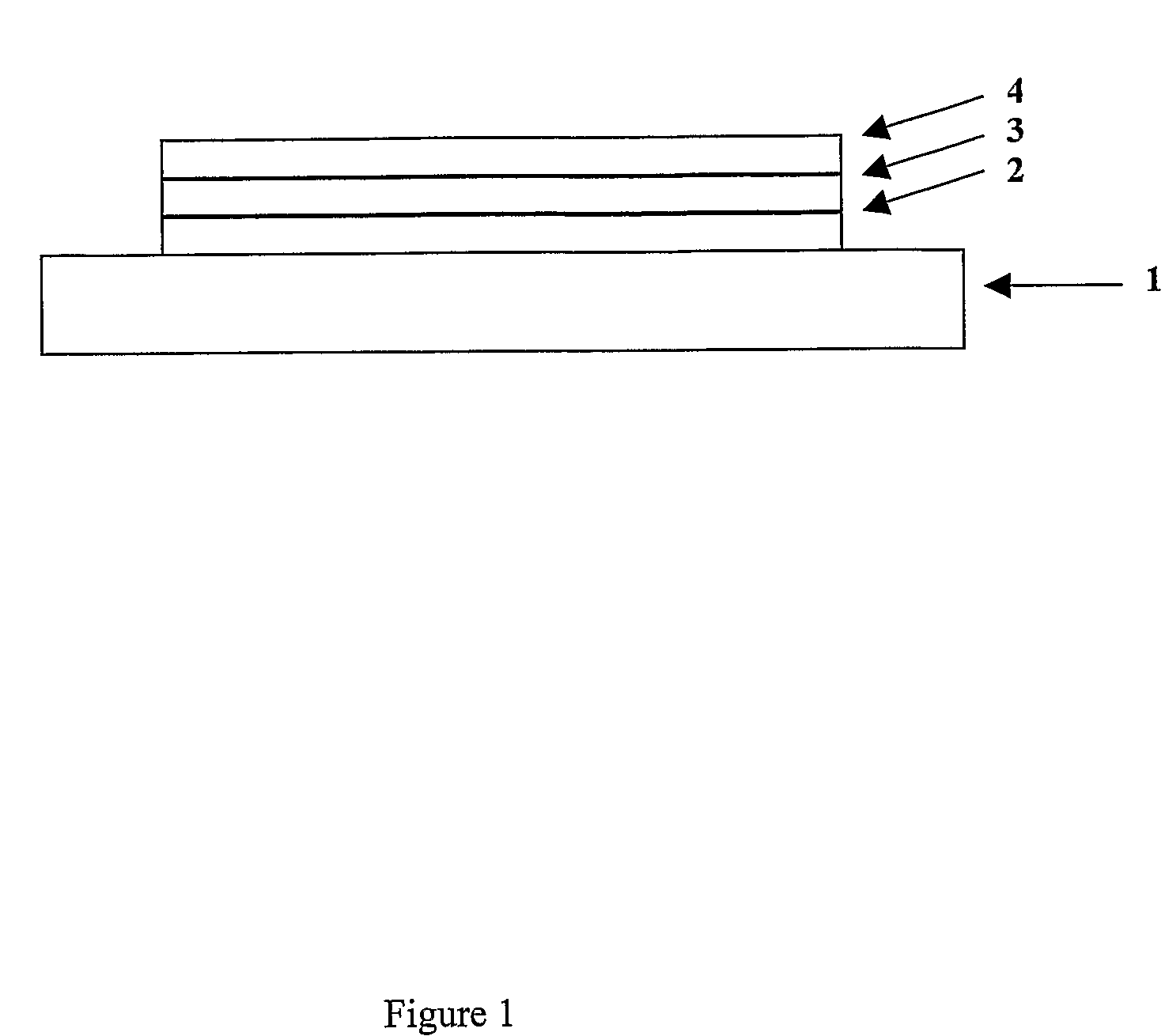
[0157]A device was formed according to the process set out below.

[0158]Poly(ethylene dioxythiophene) / poly(styrene sulfonate) (PEDT / PSS), available from H C Starck of Leverkusen, Germany as Baytron P® was deposited over an indium tin oxide anode supported on a glass substrate (available from Applied Films, Colorado, USA) by spin coating. Polymer 1 according to the invention was deposited over the layer of PEDT / PSS by spin-coating from xylene solution to a thickness of around 65 nm. A Ba / A1 cathode was formed over polymer 1 by evaporating a first layer of barium to a thickness of up to about 10 nm and a second layer of aluminium barium to a thickness...


PUM

PropertyMeasurementUnit
wavelengthaaaaaaaaaa

Abstract

A monomer for use in manufacturing a conjugated polymer, the monomer having a structure as shown formula (2):
Ar1, Ar2 and Ar3 are independently selected from optionally substituted aryl or heteroaryl, X1 and X3 both independently comprise a leaving group capable of participating in polymerisation and Z represents a direct bond or an optionally substituted bridging atom.

Description

FIELD OF INVENTION[0001]This invention relates to amines. More particularly, this invention relates to amine monomers and polymers formed from amine monomers for use as emitters and / or charge transporters and / or host materials in opto-electrical devices.BACKGROUND OF INVENTION[0002]The use of triarylamine units as emitters, hole transporters and host materials in opto-electrical devices is known as will be evident from the following description of the background to the invention which outlines a basic device structure and some known materials for use in such a structure.[0003]One class of opto-electrical devices is that using an organic material for light emission or detection. The basic structure of these devices is a light emissive organic layer, for instance a film of a poly (p-phenylenevinylene) (“PPV”) or polyfluorene, sandwiched between a cathode for injecting negative charge carriers (electrons) and an anode for injecting positive charge carriers (holes) into the organic laye...

Claims


Application Information

Patent Timeline
Patent Type & Authority Applications(United States)
IPC IPC(8): H01J1/63C07D403/10C07D209/86C07D471/04C08F26/06C08G73/06C09K11/06
CPCC07D209/88H01L31/0256C08G61/122C08G61/124C08G2261/3162C08G2261/3241C08L65/00C09K11/06C09K2211/1466H01L51/0035H01L51/0036H01L51/0039H01L51/0043H01L51/0059H01L51/0072H01L51/0085H05B33/14Y02E10/549C08G73/026C08G61/121Y02P70/50H10K85/115H10K85/113H10K85/111H10K85/151H10K85/631H10K85/6572H10K85/342H10K50/11H10K2101/10C07D221/18C09K11/07H10K85/633
Inventor LEADBEATER, MARKHEIDENHAIN, SOPHIESTEUDEL, ANNETTEHICKS, DANIEL
Owner CDT OXFORD
Why Eureka
Try Eureka