
Composite material, composite material substrate, composite material dispersed fluid, and manufacturing methods thereof

a technology of composite materials and dispersed fluid, which is applied in the direction of catalyst activation/preparation, metal/metal-oxide/metal-hydroxide catalysts, chemical/physical processes, etc., can solve the problem of not being able to oxidize a carbon-containing component, and not being able to obtain the activity of the components of the core portion in the partial oxidation catalyst, etc. problem, to achieve the effect of suppressing the generation of trivalent cerium carbon

Inactive Publication Date: 2009-08-20
TOYOTA CENT RES & DEV LAB INC
View PDF9 Cites 17 Cited by
  • Summary
  • Abstract
  • Description
  • Claims
  • Application Information

AI Technical Summary

Benefits of technology

[0009]The present invention has been made in view of the above-mentioned problem of the conventional techniques. An object of the present invention is to provide a composite material which is extremely useful as an oxidation catalyst and the like capable of oxidizing a carbon-containing component such as soot and a component such as HC, CO or NO sufficiently at a lower temperature, a composite material substrate using the material, and manufacturing methods capable of efficiently and surely obtaining the composite material and the composite material substrate.
[0025]It is preferable that the second metal oxide particulates according to the present invention be oxygen-reactive-species transporting particulates made of an oxygen-reactive-species transporting material which is capable of transporting an oxygen reactive species generated by the oxygen-extracting material. Above all, it is particularly preferable that the second metal salt serving as a raw material of the oxygen-reactive-species transporting material contain a salt of Ce and a salt of an additive metal which is at least one substance selected from the group consisting of La, Nd, Pr, Sm, Y, Ca, Ti, Fe, Zr, and Al. In the method of manufacturing a composite material of the present invention, it is possible to control the particle diameter of the aggregate by containing the salt of the additive metal.
[0035]Therefore, according to the present invention, it is possible to obtain the composite material of the present invention easily and reliably without using hard-to-use materials such as an organic solvent or using a dispersion stabilizer such as PVP and without requiring conditions such as a high temperature or an inert atmosphere. Here, a fact that a molar ratio of Ce to Ag in the aggregates obtained in the examples to be described later is around 1:1 is deemed to support validity of the speculation concerning the above-described reaction mechanism.
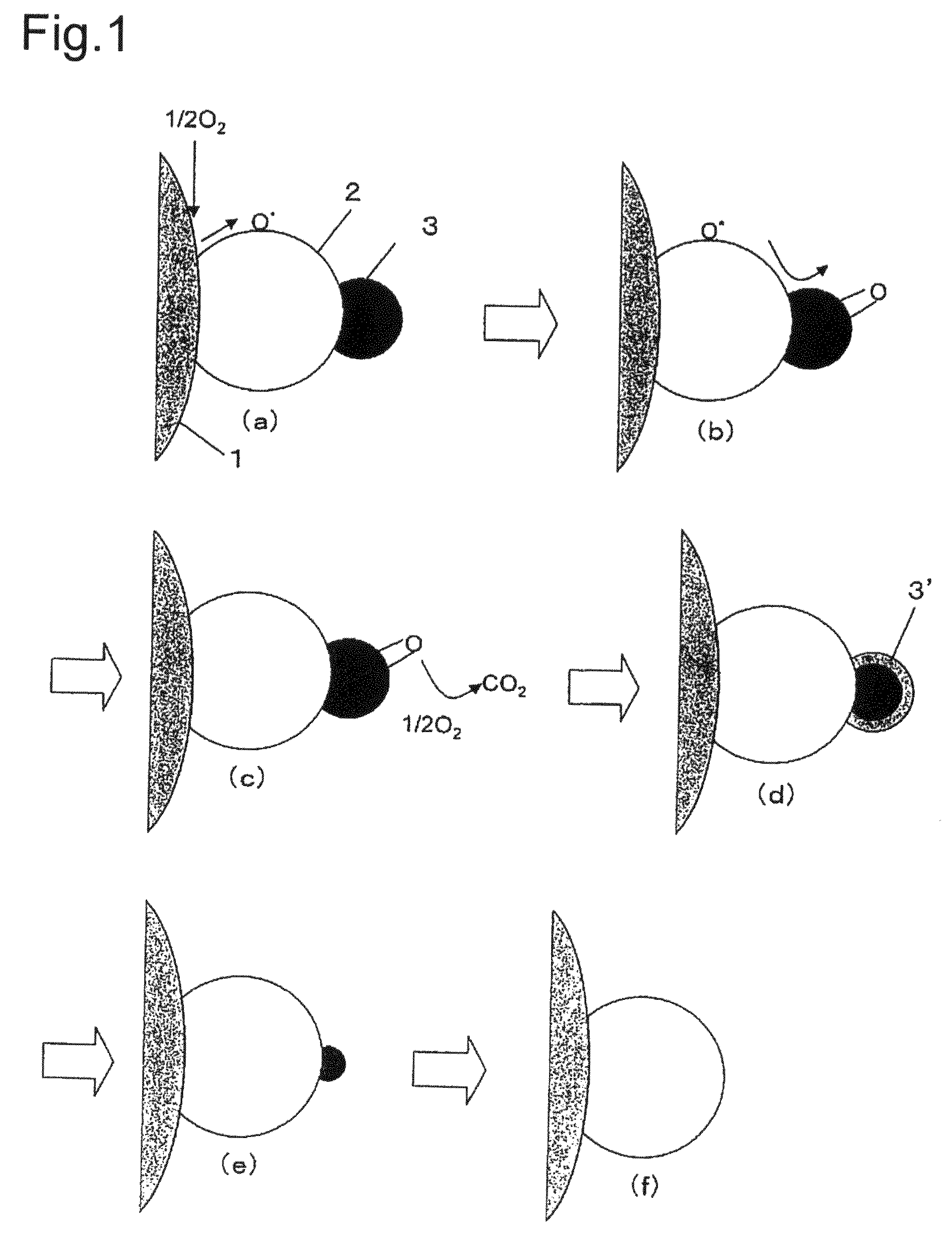
[0049]A catalyst for purification of exhaust gas, (the oxidation catalyst) using the composite material of the present invention has a high density of surface basic sites and therefore has a significant effect to promote the oxidation reaction of soot. Moreover, due to a high proportion of weak basic sites, the basic sites are regenerated and a promotive effect thereof is maintained. In addition, generation of trivalent cerium carbonate is suppressed and the effect to promote the oxidation reaction of soot is further enhanced.

Problems solved by technology

However, concerning a diesel engine, there are still many technical problems left with purification of exhaust gas because the exhaust gas contains particulates (particulate matter: such as soot composed of carbon particulates or soluble organic fractions (SOF), hereinafter referred to as PM).
Hence it was not possible to oxidize a carbon-containing component such as the soot and a component such as HC, CO or NO sufficiently at a low temperature by the catalyst compositions disclosed in Document 1, i.e. merely by presence of a set of Ag and CeO2 or a set of Co and CeO2.
However, it is hard to obtain activity of the components of the core portions in the partial oxidation catalyst having the catalytically active component that is strongly coated with the shell portion such as the catalyst disclosed in Document 2 and in the particles having the core-shell structure in which the capsular coating is formed by a condensation reaction as disclosed in Document 3.
Accordingly, it was not possible to oxidize a carbon-containing component such as soot and a component such as HC, CO or NO sufficiently at a low temperature.

Method used


Image

  • Composite material, composite material substrate, composite material dispersed fluid, and manufacturing methods thereof
  • Composite material, composite material substrate, composite material dispersed fluid, and manufacturing methods thereof
  • Composite material, composite material substrate, composite material dispersed fluid, and manufacturing methods thereof

Examples


examples

[0165]The present invention will be described below more concretely based on Examples and Comparative Examples. However, the present invention will not be limited only to the following Examples.

[0166]Although the composite materials made of CeO2 and Ag are obtained in the following Examples, it is possible to select a different combination of materials that constitute a composite material in order to obtain such a desired composite material based on the concept to be described below, for example.

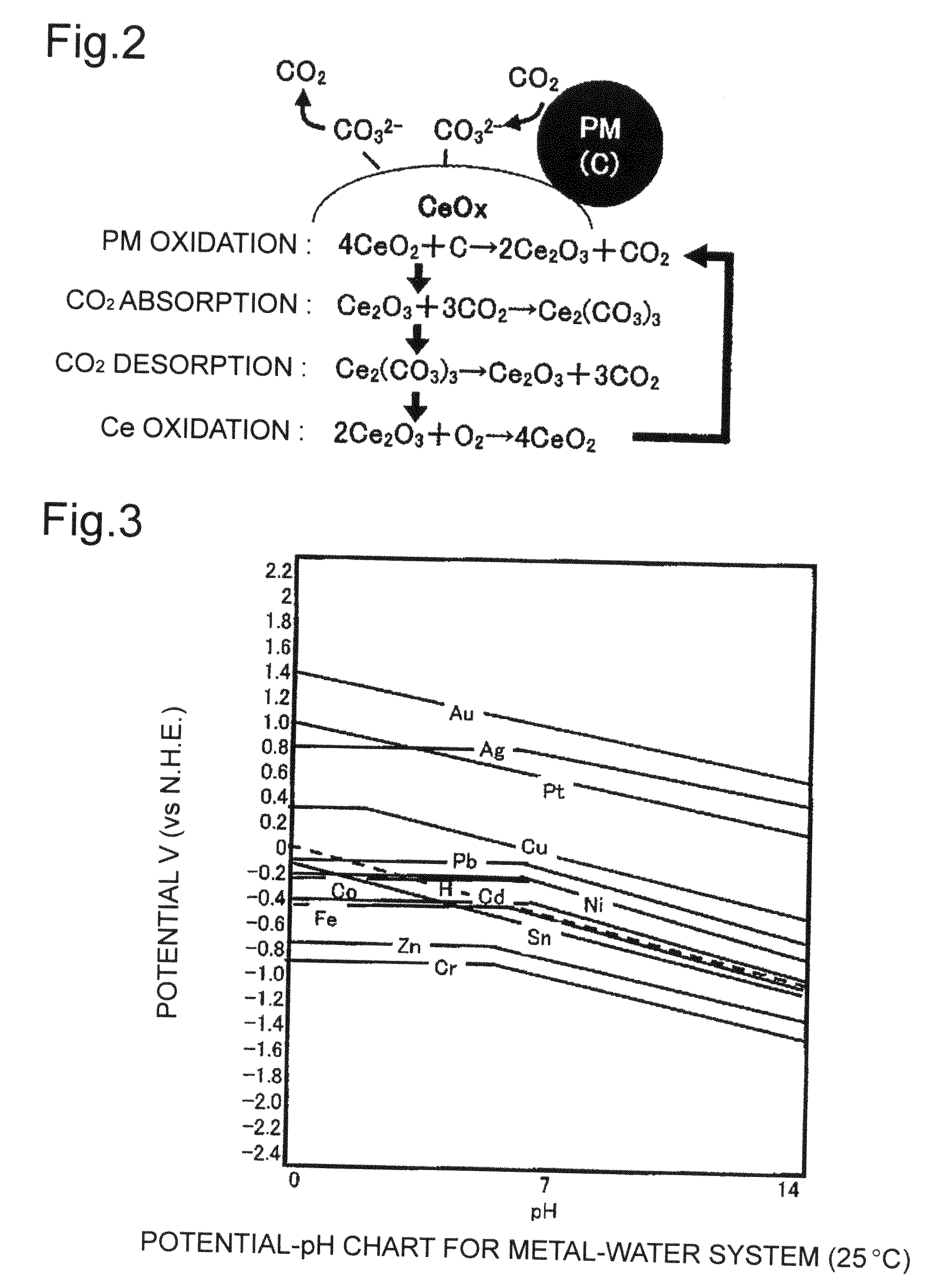
[0167]Specifically, metal oxides containing valence variable elements and precursors thereof are firstly sorted out depending on usages. For example, when selecting CeO2 for use in the oxidation catalyst as in the Examples, reduction potential of Ce(OH)3 serving as the precursor of CeO2 is grasped. Moreover, types of the metal are selected in response to the usages. Concerning the metal, deposition potential thereof is easily acquired from various documents. Here, it is preferable to select ...

examples 1 to 12

[0172]Nitrate solutions containing Ce and Ag were prepared by setting content percentages (mol %) of Ag relative to a total amount of Ce and Ag to 25 mol % (Example 1), 30 mol % (Example 2), 35 mol % (Example 3), 40 mol % (Example 4), 45 mol % (Example 5), 50 mol % (Example 6), 55 mol % (Example 7), 60 mol % (Example 8), 65 mol % (Example 9), 70 mol % (Example 10), 75 mol % (Example 11), and 80 mol % (Example 12), respectively. For instance, in Example 8, a solution was prepared by dissolving 50.49 g of Ce(NO3)3.6H2O and 29.63 g of AgNO3 into 120 mL of water. Next, ammonia water containing an amount of NH3 necessary for precipitating the nitrates was prepared. For instance, in Example 8, ammonia water was prepared by diluting 35.6 g of 25 percent ammonia water with 100 g of water. Then, the nitrate solution was blended while agitating the ammonia water (inverse precipitation) or, alternatively, the ammonia water was blended while agitating the nitrate solution (precipitation). In ea...

examples 13 to 22

[0198]CeO2—Ag-additive compositions (composite materials) containing Ag, ceria and an additive component were prepared by reverse precipitation similarly to Example 8 except that nitrate solution containing Ce, Ag and the additive component were prepared by setting content percentages (mol %) of the additive component relative to a total amount of Ce and the additive component to La 5 mol % (Example 13), La 10 mol % (Example 14), La 20 mol % (Example 15), Nd 5 mol % (Example 16), Nd 10 mol % (Example 17), Nd 20 mol % (Example 18), Pr 10 mol % (Example 19), Fe 10 mol % (Example 20), Zr 10 mol % (Example 21), and Al 10 mol % (Example 22), respectively. For instance, in Example 14, a solution was firstly prepared by dissolving 50.46 g of Ce(NO3)3.6H2O, 5.59 g of La(NO3)3, and 29.62 g of AgNO3 into 120 mL of water. Next, ammonia water was prepared by diluting 38.21 g of 25 percent ammonia water with 100 g of water. Then, the solution prepared as described above was put in while agitatin...


PUM

PropertyMeasurementUnit
Temperatureaaaaaaaaaa
Fractionaaaaaaaaaa

Abstract

A composite material includes an aggregate which contains a first metal particle constituting a core and second metal oxide particulates surrounding the first metal particle and having an average primary particle diameter ranging from 1 to 100 nm.

Description

TECHNICAL FIELD[0001]The present invention relates to a composite material and a manufacturing method thereof, a composite material substrate using the composite material, and a composite material dispersed fluid and a method of manufacturing a composite material substrate using the same.BACKGROUND OF THE INVENTION[0002]Concerning a gasoline engine, hazardous components in exhaust gas has been steadily decreased by strict regulations of exhaust gas and advance in technology that can deal with the regulations. However, concerning a diesel engine, there are still many technical problems left with purification of exhaust gas because the exhaust gas contains particulates (particulate matter: such as soot composed of carbon particulates or soluble organic fractions (SOF), hereinafter referred to as PM).[0003]Accordingly, in recent years, the oxidation catalyst capable of oxidizing the PM, particularly soot components, at low temperature have been developed. For example, Japanese Unexamin...

Claims


Application Information

Patent Timeline
IPC IPC(8): B01J23/40B01J23/00B01J23/32B01J23/02B01J23/10B01J21/06B01J23/16B01J23/52B01J23/30B01J23/42B01J23/72B01J23/50B01J23/26B01J23/28B22F1/054B22F1/16
CPCB01D53/944Y10T428/2991B01D2255/206B01D2255/40B01D2255/9022B01D2255/9202B01J23/56B01J23/63B01J23/66B01J23/68B01J23/76B01J35/0013B01J35/002B01J35/023B01J37/0215B01J37/03B22F1/0018B22F1/02B22F9/24B82Y30/00B01D2255/104B22F1/054B22F1/16B01J35/30B01J35/23B01J35/40
Inventor KAYAMA, TOMOYUKIBANNO, KOUZIYAMAZAKI, KIYOSHIYOKOTA, KOJI
Owner TOYOTA CENT RES & DEV LAB INC
Learn More