Solid-state luminescent filament lamps

Inactive Publication Date: 2009-08-27
ILLUMINATION MACHINES
View PDF4 Cites 49 Cited by
  • Summary
  • Abstract
  • Description
  • Claims
  • Application Information

AI Technical Summary

Benefits of technology

[0010]A luminescent glass or glass-ceramic filament can improve efficiency of wavelength conversion in several ways, including the elimination of thermal quenching loss and a reduction in scattering by matching the host medium with the phosphor index of refraction. Many Pb-free glasses are available with refractive index approaching 1.8 to match that of the crystalline host materials and lanthanide dopants. Implementing the luminescent filament wavelength conversion will eliminate the thermal quenching loss producing a wavelength conversion efficiency of (0.82)*(0.9)*(1.0)=0.74. The GaN emitters themselves are relatively unaffected by operation at high junction temperature. Operating the die junctions at higher temperature allows for a reduction in the size and surface area of the thermal dissipation structure

Problems solved by technology

The problem with blue light emission is that the photopic efficacy spectrum requires a large amount of green light to produce luminous flux and a white spectra requires a continuous power from 380-780 nm where in light in the green-red spectrum is of highest importance in the warm white approximating the spectral distribution of a 2700-3000 K planckian radiator.
Down converting the blue light to yellow and red produces stokes shift quantum loss which is unavoidable.
The thermal quenching of the phosphor is most problematic when the phosphor layer is directly deposited to the die structure through an electrophoretic deposition process, or through the heat generated at the chip which reduces the wavelength conversion efficiency of a luminescent ceramic chip placed directly on the blue die emitter itself, or when the phospho

Method used


Image

  • Solid-state luminescent filament lamps
  • Solid-state luminescent filament lamps
  • Solid-state luminescent filament lamps

Examples


Embodiment Construction

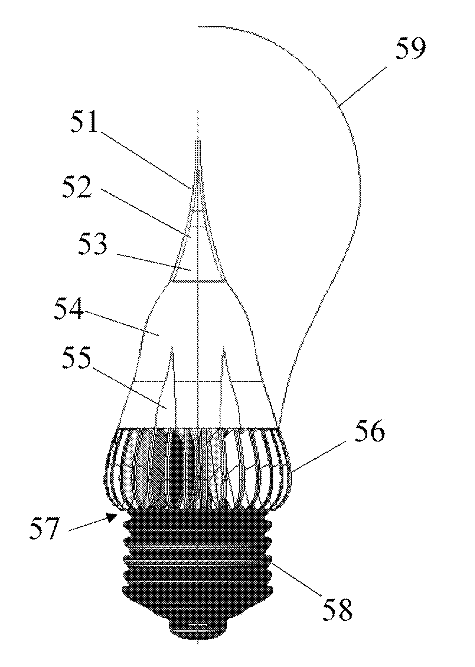
[0056]In the following detailed description of the invention of exemplary embodiments of the invention, reference is made to the accompanying drawings (where like numbers represent like elements), which form a part hereof, and in which is shown by way of illustration specific exemplary embodiments in which the invention may be practiced. These embodiments are described in sufficient detail to enable those skilled in the art to practice the invention, but other embodiments may be utilized and logical, mechanical, electrical, and other changes may be made without departing from the scope of the present invention. The following detailed description is, therefore, not to be taken in a limiting sense, and the scope of the present invention is defined only by the appended claims.

[0057]In the following description, numerous specific details are set forth to provide a thorough understanding of the invention. However, it is understood that the invention may be practiced without these specifi...


PUM

PropertyMeasurementUnit
Temperatureaaaaaaaaaa
Thicknessaaaaaaaaaa

Abstract

Traditional incandescent and halogen lamps produce a high CRI warm white light with indirect emission patterns at the cost of poor energy efficiency. This new advancement in solid-state lighting enables the production of a new solid-state filament wherein the tungsten filament is replaced with an array of high efficiency LED emitters which combine through an equiangular spiral, or t-spline/TNURCC lightpipe network to produce a single homogeneous blue light source which then pumps a luminescent filament comprised of a phosphor loaded silicone, phosphor loaded polymer, a lanthanide doped fluoro-phosphate glass, glass ceramic tape, quantum dot filled composite, or super-continuum spectrum producing photonic crystalline structure.

Description

CROSS REFERENCE TO RELATED APPLICATIONS[0001]This application claims priority from U.S. Provisional Patent Application Ser. No. 61 / 031,213, entitled “Solid-state luminescent filament lamps”, filed on 25 Feb. 2008. The benefit under 35 USC § 119(e) of the United States provisional application is hereby claimed, and the aforementioned application is hereby incorporated herein by reference.FEDERALLY SPONSORED RESEARCH[0002]Not ApplicableSEQUENCE LISTING OR PROGRAM[0003]Not ApplicableTECHNICAL FIELD OF THE INVENTION[0004]The present invention relates generally to LED's or light emitting diodes. More specifically, the present invention relates to a solid-state filament wherein the tungsten filament is replaced with an array of high efficiency LED emitters which combine through a lightguide injector and then convert wavelength and solid-angle distribution after passing through a luminescent cladding.BACKGROUND OF THE INVENTION[0005]As of 2009 GaN LED's or light emitting diodes can produce...

Claims


Application Information

Patent Timeline
IPC IPC(8): H01J1/62
CPCF21K9/52F21Y2101/02F21V29/77F21V29/89F21K9/56F21V3/0436F21V3/0463F21V3/0409F21K9/135F21V3/0418F21K9/232F21K9/61F21K9/64F21Y2115/10F21V3/061F21V3/06F21V3/062F21V3/08
Inventor BAILEY, EDWARD E.
Owner ILLUMINATION MACHINES
Why Eureka
Try Eureka