Process, system and apparatus for passivating carbonaceous materials

a carbonaceous material and passivating technology, applied in the direction of chemistry apparatus and processes, combustible gas coke oven heating, fuels, etc., can solve the problems of high cost of coatings, other dried carbonaceous materials, and so as to improve the high calorific content of coal gas. , the effect of high calorific conten

Inactive Publication Date: 2009-09-03
CORKYS CARBON & COMBUSTION +1
View PDF7 Cites 23 Cited by
  • Summary
  • Abstract
  • Description
  • Claims
  • Application Information

AI Technical Summary

Benefits of technology

[0012]It has been demonstrated that a carbonaceous material feed stream may be dried and carbonised to produce char, both processes being conducted simultaneously in a single vessel or, alternatively, the drying and carbonisation processes may be conducted sequentially in two separate vessels. The volatile matter evolved from the carbonaceous materi

Problems solved by technology

Historically, on an industrial scale, char has been an undesirable by-product of a smokeless fuel plant, coke works or coal gasification plant, although smaller scale plants produce char for activated carbon and micro blast furnaces.
Other dried carbonaceous material, in particular

Method used


Image

  • Process, system and apparatus for passivating carbonaceous materials
  • Process, system and apparatus for passivating carbonaceous materials
  • Process, system and apparatus for passivating carbonaceous materials

Examples


example

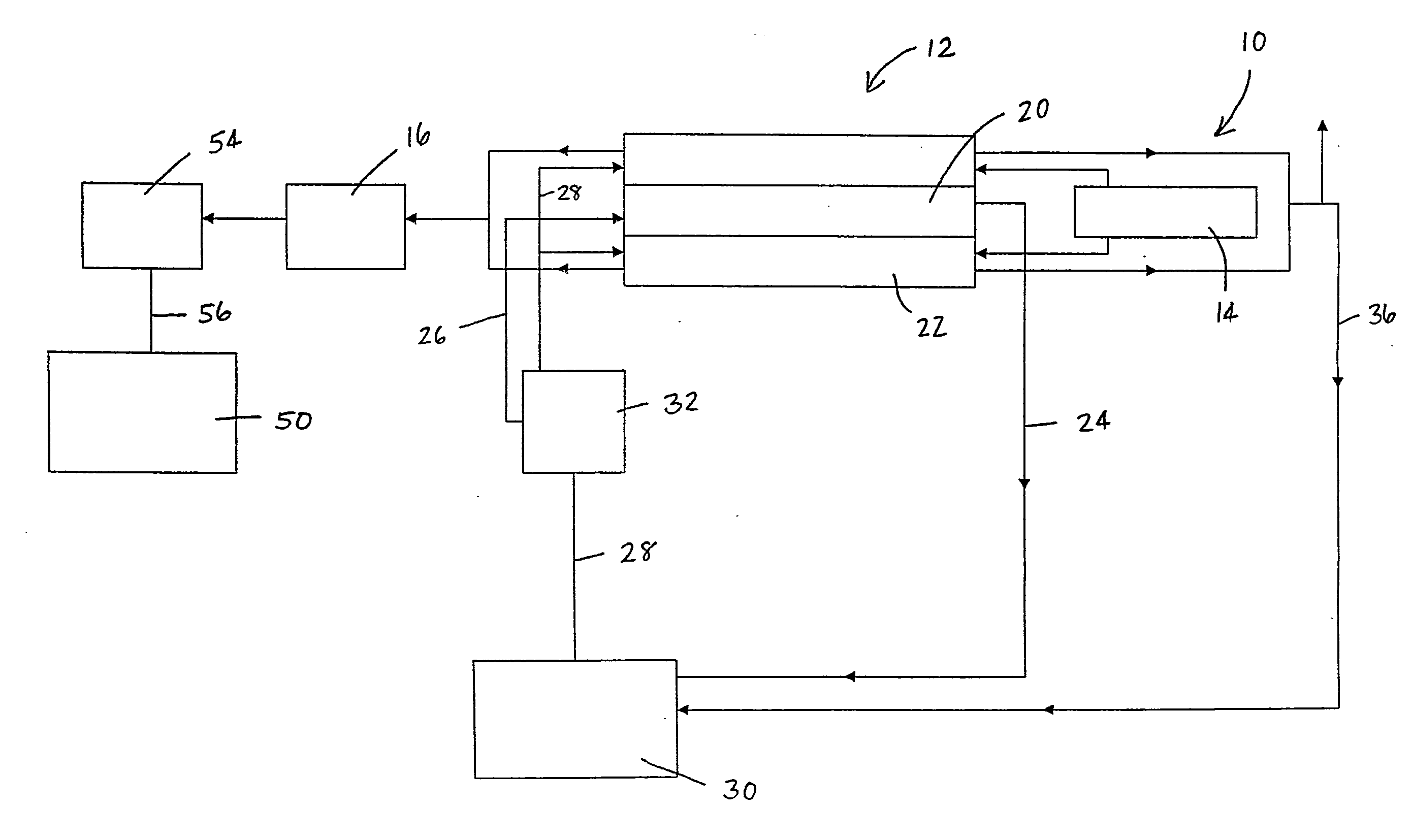
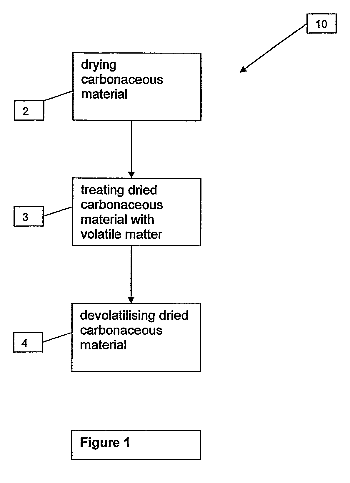
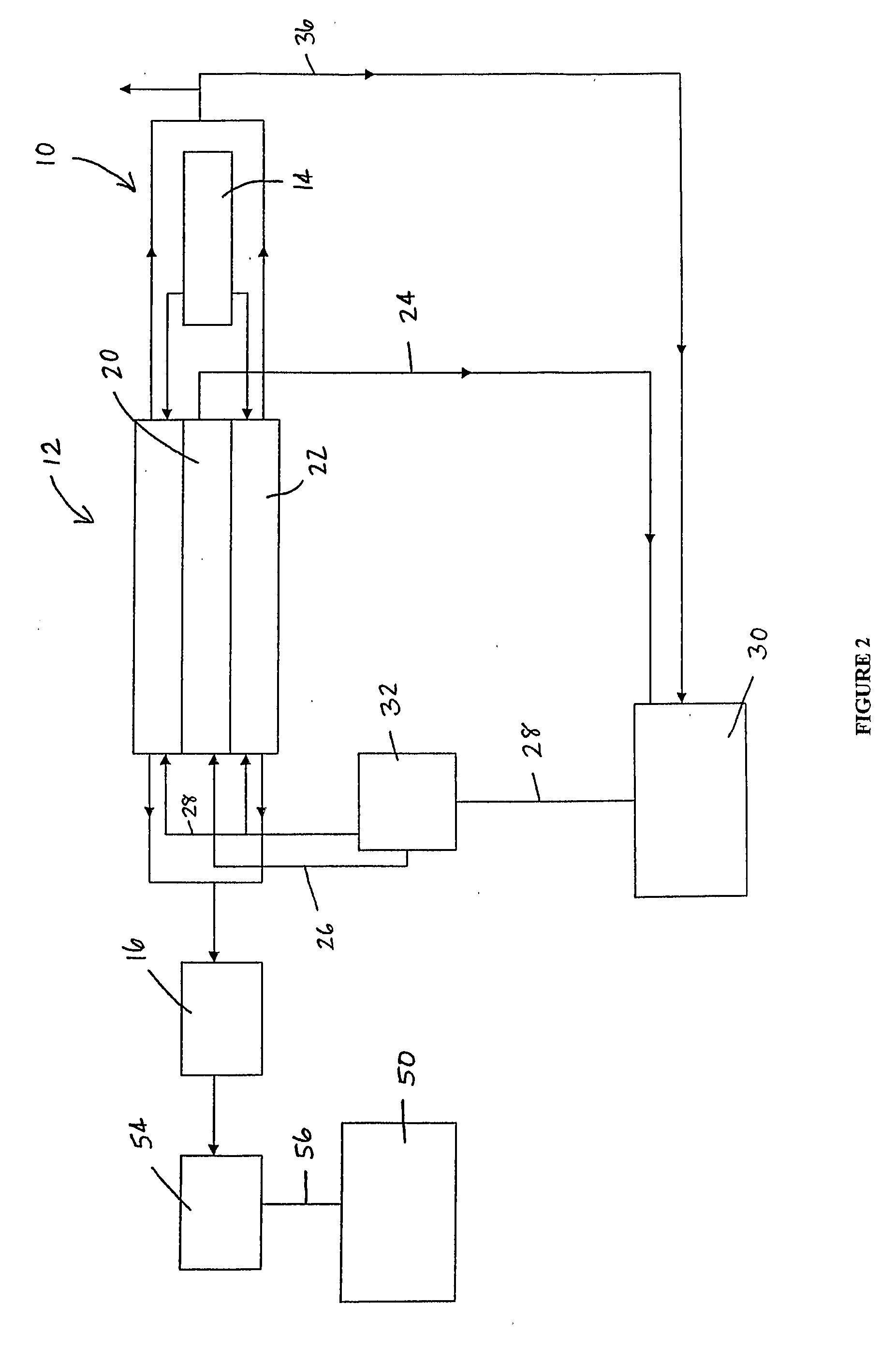
[0152]Crushed coal from the Ewington mine in Western Australia (100%-15 mm) at 28% moisture is fed at 49 tph to a 16.5-m long five cell fluidised bed dryer. The coal in the fluidised bed dryer is heated with a flow (28,500 kg / h) of waste gas containing 1.6% (m / m) O2 at temperatures of 800° C. produced in a 10 MW burner. The coal feed stream has a residence time of 9 to 10 minutes in the dryer. The last cell of the dryer is heated by the off gas generated from the pyrolising means in this system.

[0153]Hot (150° C.) dry coal is fed to a 13.2-m long refractory lined carboniser via a gas lock feeder. The dried coal is heated to 1,300° C. These high temperatures are generated by feeding hot air (800° C.) to the carboniser which combusts with some of the coal gas evolved during pyrolisis. The coal gas flows in a counter-current direction to the flow of the coal / char feed stream. The total residence time of the char feed stream held above 900° C. is between 11 and 12 minutes. Approximately...

example 2

Trial Data

[0156]Collie coal, with 24% moisture, was pre-dried in an oven under nitrogen at 120° C. This coal was then heated at 5° C. / min until it reached 300° C. The mass lost was 0.6% and the equilibrium moisture was 6.5%. The same dried coal was placed in an oven for 10 minutes at 400° C. The resulting mass loss was 2.6% and the equilibrium moisture was 4.5%. The feed coal typically has an equilibrium moisture of about 13%.

[0157]A large scale trial was performed using a rotary kiln with recycled coal gas and air dried coal. The results are presented below in Table 1. The coal residence time was 20 minutes to heat the coal to an average discharge temperature of 266° C.

TABLE 1Low Temperature Carbonized CoalTotalVola-SpecificMois-tileFixedEnergytureLevelAshCarbonSulfurMJ / kgfeed coal (gar)25.5%27.2%3.60%43.7%0.55%21.28feed coal (db)36.5%4.83%58.7%0.74%28.56carbonised 8.5%26.0% 5.5%60.0%0.66%27.4coal (gar)carbonised28.4% 6.0%65.7%0.72%29.2coal (db)

[0158]The overall yield was 65.6% on ...


PUM


Abstract

A process, system and apparatus is provided for passivating carbonaceous material against spontaneous combustion. The process involves drying the carbonaceous material in a low oxygen environment and pre-conditioning the carbonaceous material by contacting it with volatile matter contained in a countercurrent gas stream. The volatile matter coats the particles of dried carbonaceous material and plugs the micropores of the dried carbonaceous material, thereby passivating it against adsorption of water and oxygen, and thus spontaneous combustion. The pre-conditioned dried material then undergoes devolatilisation at temperatures at which volatile matter is evolved. The evolved volatile matter mixes with the countercurrent gas stream and is used to pre-condition dried carbonaceous material located upstream.

Description

FIELD OF THE INVENTION[0001]The present invention relates to a process, system and apparatus for passivating carbonaceous materials against spontaneous combustion. An apparatus for heating oxygen sensitive carbonaceous material in a controlled oxygen environment is also described.BACKGROUND OF THE INVENTION[0002]Coal pyrolysis occurs upon heating coal to produce gases, liquids, and a solid residue (char or coke). Pyrolysis occurs in all coal utilisation processes, including combustion, gasification, liquefaction, and carbonisation. The nature of pyrolysis and of the resulting products is intimately related to the operating conditions and to the composition and properties of the coal. Consequently, control of pyrolysis is important in coal utilisation processes.[0003]The principal difference between char and coke is that the parent coal for char has high oxygen content and a non-aromatic structure and therefore the char particles do not tend to agglomerate during pyrolysis. The paren...

Claims


Application Information

Patent Timeline
IPC IPC(8): C10L9/02C10L5/00C10L9/08C10L9/10
CPCC10L5/00C10L9/10C10L9/08
Inventor COLEMAN, JAMESCORK, DAVID
Owner CORKYS CARBON & COMBUSTION
Why Eureka
Try Eureka