Magneto optical device

a technology of optical devices and magnetic fields, applied in the direction of mounting heads within the housing, reproducing light beams, instruments, etc., can solve the problems of reducing the effective numerical aperture na and laser light intensity, sharp increase of laser light reflection on the coil holder-air surface, and increasing stray light. , to achieve the effect of better results

Inactive Publication Date: 2009-09-03
KONINKLIJKE PHILIPS ELECTRONICS NV
View PDF12 Cites 2 Cited by
  • Summary
  • Abstract
  • Description
  • Claims
  • Application Information

AI Technical Summary

Benefits of technology

[0007]As the numerical aperture increases up to 0.85, and beyond to 0.95 or larger than 0.85 but smaller than 1, the sine of the angle for a flat exit surface increases to values of 0.85 or <1, even 0.95. However, at rather oblique angles the laser light reflection on the coil holder-air surface increases sharply, in fact reducing the effective numerical aperture NA and the laser light intensity and increasing stray light. In a magneto-optical device an anti-reflection coating may be used to reduce the problem, however, even so large numerical apertures pose a problem with regard to the design of the anti-reflection (AR) coating that has to be applied on the head-air interface in order to optimise the transmission of the lens. This AR coating should suppress the reflection of light at this interface for both p and s polarisation for the entire angular spectrum of 0° up to Sin−1(0.95)=72°, while keeping the retardance of the coating (the phase difference between the p and s polarisation of the transmitted light) close to zero in order to avoid loss of the (polarisation sensitive) MO signal. The inventors have realized that although ever more sophisticated anti-reflection coatings may partially overcome the problem, at high angles, i.e. when the numerical aperture NA rises above 0.8 to 0.85 they fail.
[0008]In the magneto optical device in accordance with the invention, the exit surface of the coil holder is concavely shaped at the aperture with a radius of curvature R lying between 0.5 D and 15 D where D is the diameter of the concavely shaped exit surface. The exit surface is the surface from which the laser beam exits. The curvature of the exit surface allows effective anti-reflective coatings may to be made, and even without an anti-reflective coating an advantage is obtained.
[0009]Preferably the radius of curvature lies between 0.8 D and 10 D, most preferably between 1.5 D and 4 D. This allows even better results to be obtained.
[0020]This method allows to make coil holder on an industrial scale and with high precision and reproducibility. Making a recess has the advantage that the distance between the coil and the disc is smaller than without a recess.

Problems solved by technology

However, at rather oblique angles the laser light reflection on the coil holder-air surface increases sharply, in fact reducing the effective numerical aperture NA and the laser light intensity and increasing stray light.
In a magneto-optical device an anti-reflection coating may be used to reduce the problem, however, even so large numerical apertures pose a problem with regard to the design of the anti-reflection (AR) coating that has to be applied on the head-air interface in order to optimise the transmission of the lens.

Method used


Image

  • Magneto optical device
  • Magneto optical device
  • Magneto optical device

Examples


Embodiment Construction

[0035]The present invention is applicable to each and any type of magneto optical device having a read and / or write head and a laser which in operation shines through a coil. Whether the magneto optical device is of the so-called Far Field type and whether or not use is made of a slider or of an actuator.

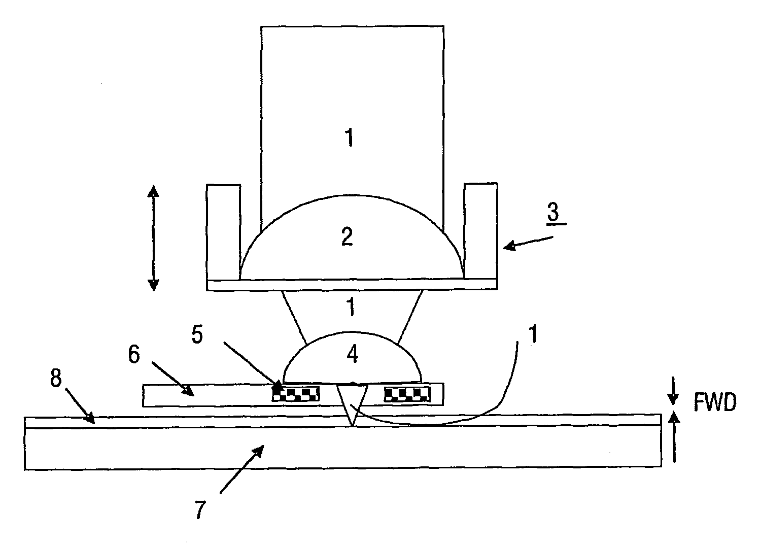
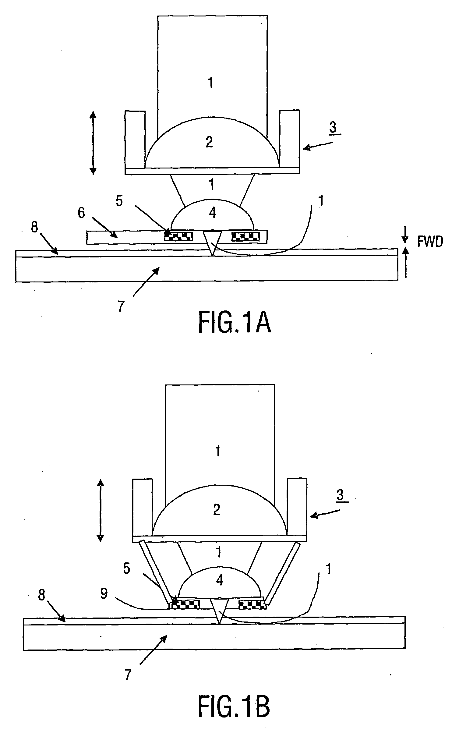
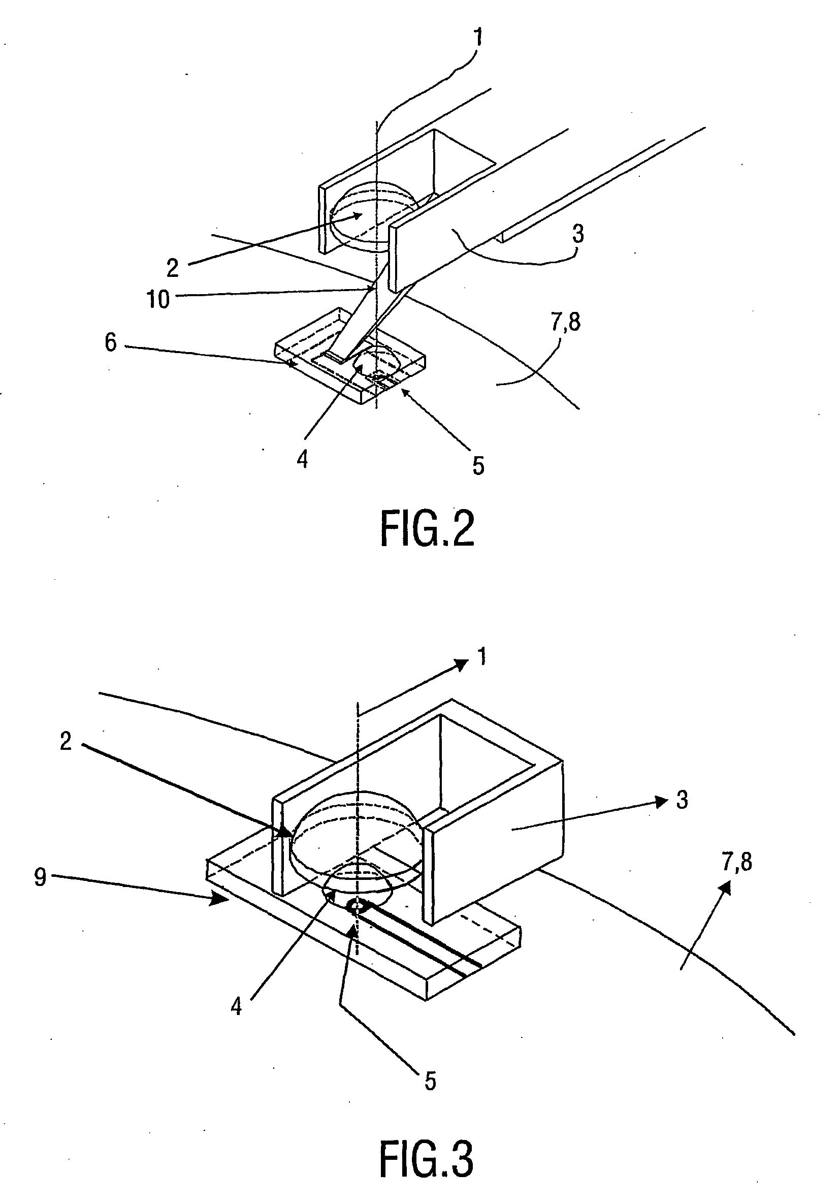
[0036]FIGS. 1A and 1B illustrates two types of arrangements. In both arrangements a laser beam 1 is in operation shone though an objective lens 2 on a holder 3, through a second lens 4 to be focused on a disk 7. The disk 7 is provided with a cover layer 8. The laser beam 1 is shone through a coil 5. FIG. 1A shows a type of read and / or write head of the so-called slider type, in which the second lens 4 and coil 5 is provided on a slider 6. FIG. 1B shows a head of the so-called actuator type in which the lens 4 and coil 5 is provided on and / or in a glass wafer 9. The Free Working distance FWD is the distance between slider 6 or glass wafer 9 and the disk 7. A typical value for the FWD...


PUM

PropertyMeasurementUnit
Electric dipole momentaaaaaaaaaa

Abstract

In a magneto optical device is which a laser beam is shone in operation through a coil (5), the coil holder (6) comprises a concavely curved exit surface with a radius of curvature R lying between 0.5 D and 15 D (0.5 D≦R≦15 D) where D is the diameter of the concavely shaped exit surface.

Description

FIELD OF THE INVENTION[0001]The invention relates to a magneto optical device comprising a magneto optical read and / or write head with a coil on a coil holder, the coil holder comprising a transparent aperture in the coil for passing a laser beam.[0002]The invention also relates to a method for producing a magneto optical device comprising a magneto optical read and / or write head with a coil on a coil holder, and a means for generating a laser beam, wherein in operation the laser beam is shone through an aperture in the coil.BACKGROUND OF THE INVENTION[0003]An embodiment of a system of the type mentioned in the opening paragraph is known from U.S. Pat. No. 6,069,853.[0004]In such devices optical recording techniques are combined with a magneto optical head that in operation is brought close to a recording layer on a disk. Laser light is used to read and / or write on the disk. The laser beam is shone through the coil which is e.g. incorporated on a slider or on an actuator. New genera...

Claims


Application Information

Patent Timeline
IPC IPC(8): G11B11/00G11B5/127G11B5/105G11B11/105
CPCG11B11/10536Y10T29/49066G11B11/10554G11B5/105G11B11/10G11B5/10
Inventor ZIJP, FERRYVULLERS, RUDOLF JOHAN MARIA
Owner KONINKLIJKE PHILIPS ELECTRONICS NV
Why Eureka
Try Eureka