Method of forming a magnetic tunnel junction structure

a magnetic tunnel junction and structure technology, applied in the direction of magnetic field-controlled resistors, digital storage, instruments, etc., can solve the problems of slow etch rate, undesired film loss, corner rounding, etc., to improve the process window for forming mtj structures, reduce erosion and corner rounding, and improve the effect of oxidation and erosion

Active Publication Date: 2009-09-10
QUALCOMM INC
View PDF4 Cites 32 Cited by
  • Summary
  • Abstract
  • Description
  • Claims
  • Application Information

AI Technical Summary

Benefits of technology

[0007]One particular advantage provided by embodiments of the disclosed methods of forming a magnetic tunnel junction (MTJ) structure is that oxidation, erosion and corner rounding can be reduced by using a trench to define dimensions of the MTJ structure without photo / etching the MTJ structure. In general, the trench is formed in an oxide base substrate, which is easier to photo-etch than the MTJ metal films. Further, it is easier to precisely photo-etch the oxide base substrate than the metal layers. Instead, a reverse trench photo-etch process and a Chemical-Mechanical Planarization (CMP) process can be used to remove excess material, without introducing erosion, corner rounding or other issues that may impact performance of the MTJ structure.
[0008]Another particular advantage is provided in that a process window for formation of MTJ structures is improved, i.e., enlarged, and the overall reliability of MTJ process and resulting MTJ structure is also improved.

Problems solved by technology

Unfortunately, the MTJ stack may include magnetic films that are basically metal films and that have a relatively slow etch rate, so the hard mask may need to be relatively thick.
However, while these additional layers increase process complexity (both in terms of additional deposition processes and in terms of additional layer photo / etch and clean processes), the MTJ cell structure may experience erosion, which may result in an undesired slope, corner rounding, and undesired film loss.
Such damage can impact a contact resistance of the MTJ structure and potentially even expose or damage the MTJ junction.

Method used


Image

  • Method of forming a magnetic tunnel junction structure
  • Method of forming a magnetic tunnel junction structure
  • Method of forming a magnetic tunnel junction structure

Examples


Embodiment Construction

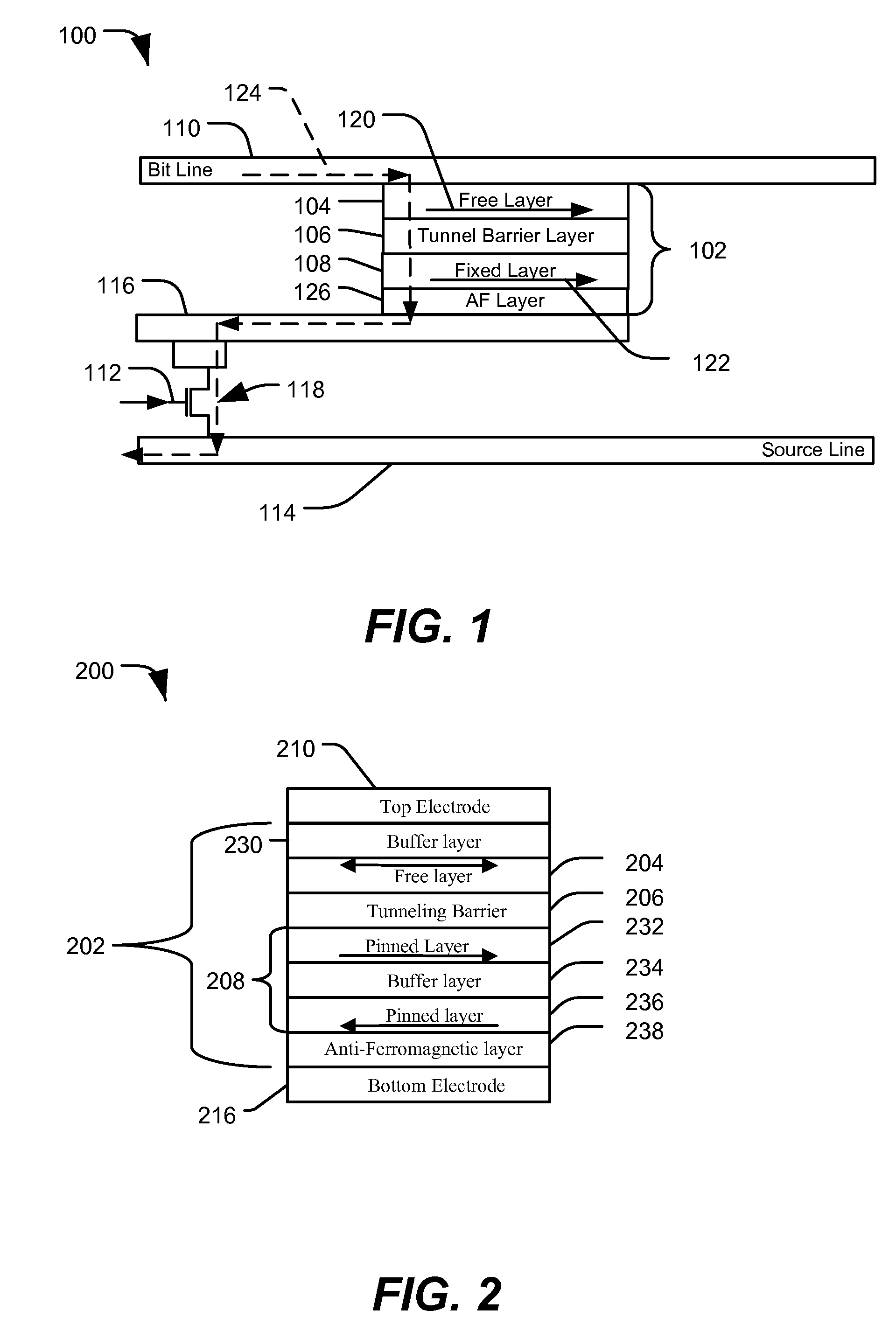
[0034]FIG. 1 is a cross-sectional view of a particular embodiment of a portion of a magnetic tunnel junction (MTJ) cell 100, which may be formed according to the methods and embodiments described with respect to FIGS. 3-24. The MTJ cell 100 includes an MTJ stack 102 having a free layer 104, a tunnel barrier layer 106, a fixed (pinned) layer 108, and an anti-ferromagnetic (AF) layer 126. The MTJ stack 102 is coupled to a bit line 110. Further, the MTJ stack 102 is coupled to a source line 114 via a bottom electrode 116 and a switch 118. A word line 112 is coupled to a control terminal of the switch 118 to selectively activate the switch 118 to allow a write current 124 to flow from the bit line 110 to the source line 114. In the embodiment shown, the fixed layer 108 includes a magnetic domain 122 that has a fixed orientation. The free layer 104 includes a magnetic domain 120, which is programmable via the write current 124. As shown, the write current 124 is adapted to program the or...


PUM


Abstract

In a particular illustrative embodiment, a method of forming a magnetic tunnel junction (MTJ) device is disclosed that includes forming a trench in a substrate. The method further includes depositing a magnetic tunnel junction (MTJ) structure within the trench. The MTJ structure includes a bottom electrode, a fixed layer, a tunnel barrier layer, a free layer, and a top electrode. The method also includes planarizing the MTJ structure. In a particular example, the MTJ structure is planarized using a Chemical Mechanical Planarization (CMP) process.

Description

I. FIELD[0001]The present disclosure is generally related to a method of forming a magnetic tunnel junction (MTJ) structure.II. DESCRIPTION OF RELATED ART[0002]In general, widespread adoption of portable computing devices and wireless communication devices has increased demand for high-density and low-power non-volatile memory. As process technologies have improved, it has become possible to fabricate magneto-resistive random access memory (MRAM) based on magnetic tunnel junction (MTJ) devices. Traditional spin torque tunnel (STT) junction devices are typically formed as flat stack structures. Such devices typically have two-dimensional magnetic tunnel junction (MTJ) cells with a single magnetic domain. An MTJ cell typically includes a bottom electrode, an anti-ferromagnetic layer, a fixed layer (i.e., a reference layer formed from a ferromagnetic material that carries a magnetic field having a fixed or pinned orientation by an anti-ferromagnetic (AF) layer), a tunnel barrier layer ...

Claims


Application Information

Patent Timeline
Patent Type & Authority Applications(United States)
IPC IPC(8): H01L43/12
CPCH01L43/08G11C11/161H01L43/12H10N50/10H10N50/01
Inventor LI, XIA
Owner QUALCOMM INC
Why Eureka
Try Eureka