Process for Producing a Nanoporous Layer of Nanoparticles and Layer Thus Obtained

a nanoporous layer and nanoparticle technology, applied in the field of nanoporous layer production or forming, can solve the problems of limited dry route, limited liquid/powder (suspension) mixture stability, and no simple implementable technique for obtaining coatings or nanoparticle layers

Active Publication Date: 2009-10-01
COMMISSARIAT A LENERGIE ATOMIQUE ET AUX ENERGIES ALTERNATIVES
View PDF10 Cites 107 Cited by
  • Summary
  • Abstract
  • Description
  • Claims
  • Application Information

AI Technical Summary

Benefits of technology

[0201]Furthermore, according to the invention it is possible to functionalise, in a different and specific manner, various, porous surfaces, zones of the layer(s) or membrane(s), thereby enabling these membranes to be used for selective retention. Likewise, in the case of several layers, it is possible to functionalize each layer in a different manner.
[0202]The spraying process of the present invention is easily carried out on an industrial scale since its specificity resides in particular in the injection system, which can be fitted to any thermal spraying machine already present in the industry, in the nature of the sol-gel solution and in the choice of the plasma conditions for obtaining a nanostructured coating having the properties of the sprayed particles.

Problems solved by technology

At the present time there is no simply implementable technique for obtaining coatings or layers of nanoparticles that meet the ever increasing requirements of structural homogeneity, thickness homogeneity, even on the scale of a few microns, mechanical strength and controlled porosity because of the miniaturization of electromechanical and / or optical and / or electrochemical microsystems.
The dry route is limited by the size of the particles that can be injected into the plasma.
The wet route overcomes this physical limitation, but is itself limited by the stability of the liquid / powder (suspension) mixtures.
In addition, the coatings obtained have the drawback of having microcracks, especially in the case of ceramic films, brittle materials which thus relieve the internal stresses.
This therefore clearly limits a priori the potential applications of plasma spraying.
Now, it is not possible at the present time to make particles smaller in diameter than one micron penetrate into a plasma jet using a conventional injector with a carrier gas, without considerably disturbing the latter.
This results in superconducting ceramic deposits, films, but these do not have a nanoscale structure and even less a nanoporous structure.
In addition, this process is not easily industrializable as it requires the use of two to four plasma torches operating simultaneously.
This technique is limited to radiofrequency plasmas and the resulting films are neither nanostructured nor nanoporous.
However, the final material is the result of an in-flight chemical reaction in the plasma, making the method complicated to control.
However, the thickness of the deposits, films formed cannot exceed around ten microns and it is not possible to produce all types of material.
The injected solution is limited to solutions of metallic materials.
The problems associated with the plasma technique are therefore very numerous, as are the solutions proposed, but none of these solutions presently allows all these problems to be solved.
These various techniques result in thin films having a thickness of generally less than one micron.
However, the coatings obtained by these processes crack beyond critical thicknesses of the order of one micron.
The main cause of this major defect lies in the tensile stresses applied by the substrate during the heat treatments necessary for producing them.
Another drawback lies in the impossibility of depositing homogeneous coatings having good adhesion, even for thicknesses greater than a few microns.
The problems associated with this other technique are therefore also very numerous, even though recent techniques have allowed some of them to be solved by acting on the chemical composition of the sol-gel solutions.
This type of membrane is not thermally and chemically stable.
However, they remain more difficult to implement.
This patent is limited to tubular geometries.
To summarise, none of these techniques of the prior art allows a nanoporous coating of nanoparticles with a thickness greater than 10 μm to be obtained.
These techniques do not indicate a promising way of simply achieving this and are limited to simple geometries, for example tubular or planar geometries.
Furthermore, these techniques are generally less productive in so far as they require the use of a combination of several processes for the final forming operation.

Method used


Image

  • Process for Producing a Nanoporous Layer of Nanoparticles and Layer Thus Obtained
  • Process for Producing a Nanoporous Layer of Nanoparticles and Layer Thus Obtained
  • Process for Producing a Nanoporous Layer of Nanoparticles and Layer Thus Obtained

Examples


example 2

[0269]Example 2 describes the manufacture of an ultrafiltration membrane on a ceramic support.

[0270]A porous alumina / titania substrate was produced beforehand by thermal spraying. Its porosity was 35% and its thickness 0.7 mm.

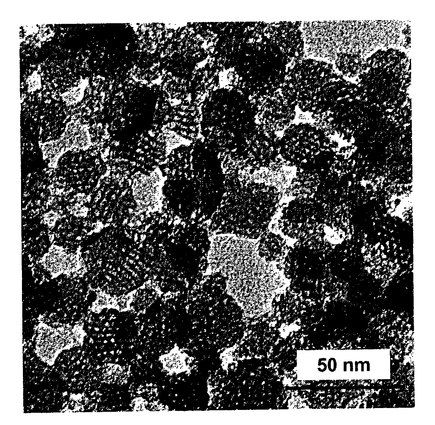
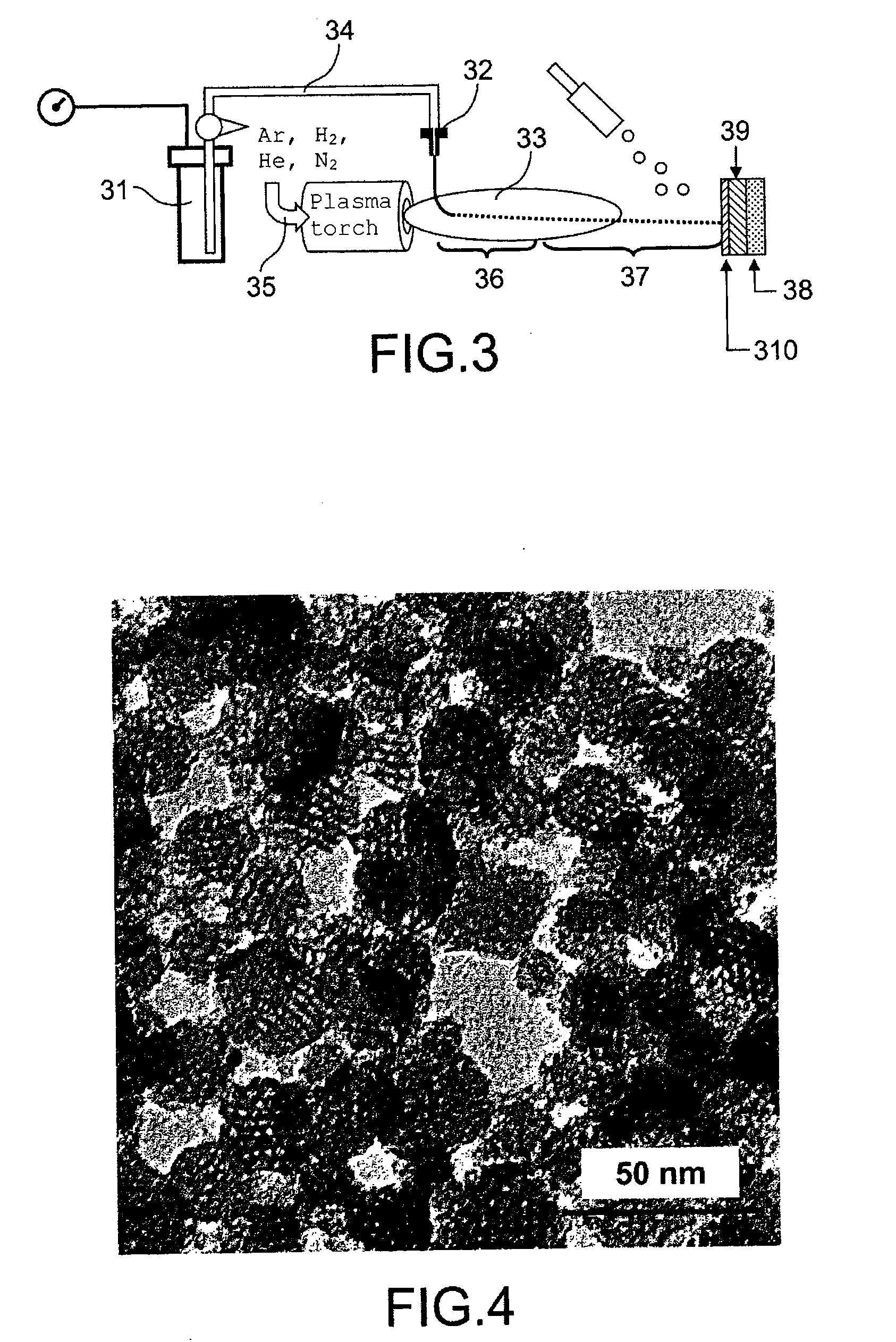
[0271]A 5% aqueous silica sol, with a particle size of 60 nm, was mixed with 7.5 wt % of a monodisperse alumina powder of 150 nm particle size. This mixture was injected into the hot (8000-15000 K) zone of a thermal plasma under the same conditions as in Example 1 and using the same means. A 30 μm thick deposit, film with a pore size of 30 nm, corresponding to the specific requirements of an ultrafiltration membrane, was obtained. The permeance of the multilayer stack (metal support / Al2O3 intermediate layer / selective membrane) was about 800 Sl / min / bar / m2. FIG. 7 is a micrograph of a section through this membrane.

[0272]FIG. 8 may be examined in relation to Examples 1 and 2.

[0273]Example 1 (left-hand diagram in FIG. 8) shows the formation of a membrane having a p...

example 3

[0275]Example 3 describes the production of an ultrafiltration membrane on a ceramic support.

[0276]A 10% aqueous mesoporous silica sol of particle size 40 nm was injected into a thermal plasma under the same conditions as in Example 1 and using the same means.

example 4

[0277]Example 4 describes the production of a phase separation membrane on a ceramic support.

[0278]A porous alumina / titania substrate was produced beforehand by thermal spraying. Its porosity was 35% and its thickness 0.7 mm.

[0279]A 5% aqueous silica sol of particle size 60 nm was mixed with 7.5 wt % of a monodisperse alumina powder of 150 nm particle size. This mixture was injected into a thermal plasma under the same conditions as in Example 1 and using the same means. A film with a thickness of 30 μm and a pore size of 30 nm was obtained.

[0280]The supported membrane was immersed in water at 80° C. for 5 h and then heated in an oven at 110° C. for 10 h. It was then dipped into a fluorinated solvent containing 1% of a fluoroalkoxysilane (CF3(CH2)5Si (OCH3)3) derivative for 48 h. A heat treatment at 130° C. for 1 h 30 min created a covalent bond between the silane and the metal oxide, forming the membrane. The membrane was thus hydrophobic. The contact angle of a water drop was abou...


PUM

PropertyMeasurementUnit
sizeaaaaaaaaaa
pore sizeaaaaaaaaaa
porosityaaaaaaaaaa

Abstract

Process for producing at least one nanoporous layer of nanoparticles chosen from nanoparticles of a metal oxide, nanoparticles of metal oxides, and mixtures of said nanoparticles, on a surface of a substrate, in which at least one colloidal sol, in which said nanoparticles are dispersed and stabilized, is injected into a thermal plasma jet which sprays said nanoparticles onto said surface.
Nanoporous layer and device, especially a separation device, comprizing said layer.

Description

TECHNICAL FIELD[0001]The present invention relates to a process for producing, or forming, a nanoporous layer of nanoparticles on a surface of a substrate.[0002]The present invention also relates to a nanoporous layer of nanoparticles capable of being obtained (obtainable) by this process.[0003]More precisely, the present invention relates to a process for producing a nanoporous membrane and to the membrane thus produced.[0004]The present invention also relates to devices comprising a nanoporous layer capable of being obtained (obtainable) by the process of the invention.[0005]The technical field of the invention may in general be defined as that of nanostructured materials, more particularly this technical field is that of nanoporous materials in the form of layers, especially thin layers usually called membranes, having a thickness for example of 1 to 100 μm.[0006]Such membranes are applicable in the fields of ultrafiltration, purification, separation of gases or of different phas...

Claims


Application Information

Patent Timeline
Patent Type & Authority Applications(United States)
IPC IPC(8): B32B3/26C23C4/10B01D39/14
CPCB01D61/027Y10S55/05B01D67/0048B01D67/0069B01D69/02B01D69/12B01D71/024B01D2323/34B01D2323/42B01D2325/022B01D2325/023C04B41/009C04B41/5089C04B41/52C04B41/85C04B41/89C04B2111/00801C23C4/121C23C4/127B01D61/145C04B41/4527C04B41/4582C04B41/5031C04B41/4933C04B35/10C04B35/00C04B35/46C04B35/478C04B38/00C23C4/11C23C4/134Y10T428/249969
Inventor PINTAULT, BRUNOGUENADOU, DAVIDBIANCHI, LUCBELLEVILLE, PHILIPPEVALLE, KARINEBOSCHER, CHRISTOPHETOULC'HOAT, JOEL
Owner COMMISSARIAT A LENERGIE ATOMIQUE ET AUX ENERGIES ALTERNATIVES
Why Eureka
Try Eureka