Enhanced steam cycle utilizing a dual pressure recovery boiler with reheat

a steam cycle and recovery boiler technology, applied in steam generation plants, steam generation using hot heat carriers, lighting and heating apparatus, etc., can solve the problems of not teaching or suggesting any way to enhance the electrical generating capability of the overall plant, the potential for corrosion in the lower furnace of recovery boilers is significant, etc., to achieve a large increase in electrical generation, enhance the steam cycle, and reduce the material of the furna

Inactive Publication Date: 2009-10-01
THE BABCOCK & WILCOX CO
View PDF16 Cites 22 Cited by
  • Summary
  • Abstract
  • Description
  • Claims
  • Application Information

AI Technical Summary

Benefits of technology

[0019]The present invention takes advantage of the flexibility of the dual pressure recovery boiler furnace construction and allows the use of an enhanced steam cycle utilizing a dual pressure recovery boiler with reheat to achieve a large increase in electrical generation with various turbine cycles while overcoming traditional lower furnace material limitations. The present invention is able to provide steam to two separate turbine stages, one high pressure and the other low pressure, off of two different steam flows at different pressures, emanating from the dual pressure recovery boiler.

Problems solved by technology

The potential for corrosion in the lower furnace of recovery boilers is a significant issue.
All these approaches are extremely expensive.
However, that design still deals with the lower furnace corrosion concerns of the prior art in conventional fashion; i.e., the steam pressure in the furnace walls low enough such that excessive corrosion does not take place in the water-cooled tube walls of the furnace.
Heat may be recovered for preheating the boiler feed water or combustion air, in the separate water circulation system; however, the separate water circulation system is not in communication with the water / steam circulation system, and the purpose of the construction is not to provide increased electrical generation capacity but rather to maintain the temperature of the medium flowing in the lower section of the separately cooled furnace nearly constant by regulating the cooling effect of the heat exchanger in the cooling circulation system to address thermal expansion concerns that might cause sealing problems between the separately cooled lower section of the furnace to correlate with the thermal expansion of the walls within the boiler water / steam circulation systems.
However, Graves et al. does not teach or suggest any way to enhance the electrical generating capability of the overall plant.

Method used


Image

  • Enhanced steam cycle utilizing a dual pressure recovery boiler with reheat
  • Enhanced steam cycle utilizing a dual pressure recovery boiler with reheat
  • Enhanced steam cycle utilizing a dual pressure recovery boiler with reheat

Examples


first embodiment

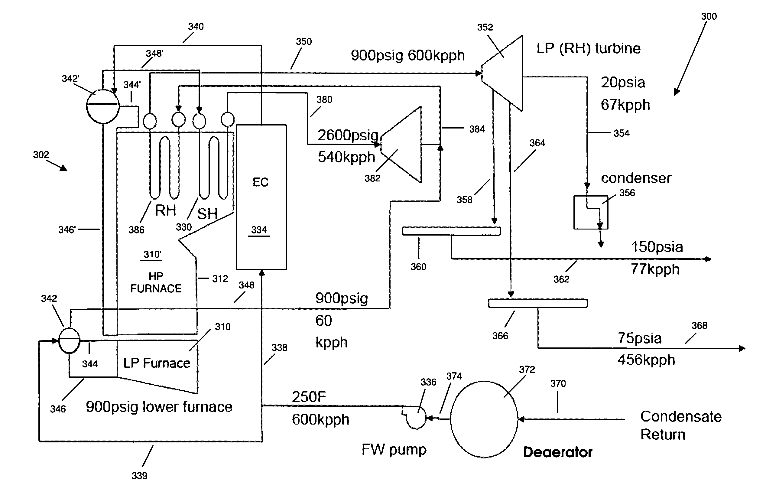
[0046]Referring to the drawings generally, wherein like reference numerals designate the same or functionally similar elements throughout the several drawings, and to FIG. 3 in particular, there is shown a schematic illustration of the present invention, comprising a dual pressure recovery boiler employed as part of a reheat steam cycle steam turbine installation, generally referred to as 300. In this embodiment, low pressure (LP) steam is mixed with high pressure (HP) steam turbine exhaust and then reheated. In this and the following Figs., and solely for the sake of convenience to the reader, the “200” series of reference numerals refer to elements in FIG. 2, while the “300” series of reference numerals refer to elements in FIG. 3, etc. Similarly, the last two numbers in the various reference numerals designate the same or functionally similar elements throughout the several drawings; e.g., 234, 334, 434 etc. refers to the economizer in FIGS. 2, 3 and 4 etc. Also, temperatures (de...

second embodiment

[0055]FIG. 4 is a schematic illustration of the present invention, comprising a dual pressure recovery boiler employed as part of a reheat steam cycle steam turbine installation, generally referred to as 400. Here, low pressure (LP) steam is used for feed water heating.

[0056]As illustrated therein, recovery boiler 402 comprises a dual pressure furnace having a LP section 410 and a high pressure section 410′. Black liquor combusted within the recovery boiler 402 furnace generates hot gases which flow across the heat transfer surfaces. In this embodiment, RH surface 486 is provided, in addition to high pressure superheater (HPSH) surface 430 and high pressure economizer (HPEC) surface 434.

[0057]Feedwater pumps 436 and 459 provide feedwater via line 438 to HPEC 434, and then via line 440 to HP steam drum 442′ which is part of the HP furnace 410′ circuit, and also to the lower LP furnace 410 via line 439. HP steam from the HP steam drum 442′ is conveyed via high pressure saturated conne...

third embodiment

[0060]FIG. 5 is a schematic illustration of the present invention, comprising a dual pressure recovery boiler employed as part of a reheat steam cycle steam turbine installation, generally referred to as 500. In this case, low pressure (LP) steam is used for process steam.

[0061]As illustrated therein, recovery boiler 502 comprises a dual pressure furnace having a LP section 510 and a high pressure section 510′. Black liquor combusted within the recovery boiler 502 furnace generates hot gases which flow across the heat transfer surfaces. In this embodiment, RH surface 586 is provided, in addition to high pressure superheater (HPSH) surface 530 and high pressure economizer (HPEC) surface 534.

[0062]Feedwater pump 536 provides feedwater to HPEC 534 via line 538 and then via line 540 to HP steam drum 542′, which is part of the HP furnace 510′ circuit, and also to the lower LP furnace 510 via line 539. HP steam from the HP steam drum 542′ is conveyed via high pressure saturated connection...


PUM


Abstract

An enhanced steam cycle utilizing a dual pressure recovery boiler with reheat allows a large increase in electrical generation with various turbine cycles while overcoming traditional lower furnace material limitations. A dual pressure designed recovery boiler furnace is provided with a lower furnace and an upper furnace. The lower furnace is operated at a lower temperature to prevent or reduce corrosion of the lower furnace wall tubes caused by the reducing environment. The lower furnace can be either a low pressure natural circulation steam generating (drum) system or economizer. Unlike the lower furnace, the upper furnace is not exposed to a reducing environment and is therefore not as susceptible to severe corrosion rates. The upper furnace is operated at higher temperatures and pressures which permit implementation of higher efficiency reheat steam cycles. The upper furnace thus operates as a high pressure natural circulation steam generating (drum) system, or as a once-through supercritical steam generating system. The dual pressure recovery boiler can thus be coupled to a variety of condensing, non-condensing or a combination of condensing and non-condensing turbine cycles to provide a large increase in electrical generation.

Description

FIELD AND BACKGROUND OF THE INVENTION[0001]1. Field of the Invention[0002]The present invention relates to the field of power generation and industrial boiler design, including Kraft process recovery boilers or soda process recovery boilers used in the pulp and paper industry. In particular, the present invention provides a new and useful dual pressure recovery boiler installation which employs an enhanced steam cycle with reheat to achieve a large increase in electrical generation with various turbine cycles while overcoming traditional lower furnace material limitations.[0003]2. Description of the Related Art[0004]The recovery boiler is utilized by the pulp and paper industry to provide a means for recovery of certain chemicals created as part of the pulping and papermaking process, electrical generation through a steam turbine, and production of process steam used by the mill in the pulping and papermaking process.[0005]For a general discussion of chemical and heat recovery in th...

Claims


Application Information

Patent Timeline
Patent Type & Authority Applications(United States)
IPC IPC(8): F22B1/18
CPCF22B33/14F22B33/10Y02P60/80
Inventor MONACELLI, JOHN E.HICKS, TIMOTHY E.HINER, LARRY A.OSBORNE, STEVEN L.
Owner THE BABCOCK & WILCOX CO
Why Eureka
Try Eureka