[0011]An
advantage of some aspects of the invention is that the invention provides a capacitive input device capable of making a light-transmitting substrate unnoticeable while simplifying a manufacturing process, a
display device provided with an
input function, and an electronic apparatus.
[0013]In the capacitive input device of the present invention, the
first light-transmitting electrodes and the second light-transmitting electrodes are formed on the same surface of the light-transmitting substrate, and thus the light-transmitting substrate is not interposed between the first light-transmitting electrodes and the second light-transmitting electrodes. By using an anti-reflective technique, it is possible to decrease a difference in reflectance between a region where the first light-transmitting electrodes are formed, a region where the second light-transmitting electrodes are formed, and a region where these light-transmitting electrodes are not formed, thereby easily making the light-transmitting electrodes unnoticeable and simplifying the manufacturing process. Also, in the present invention, as the anti-reflective technique, the multi-layer film including light-transmitting thin films having different refractive indexes and including the
niobium oxide film is formed between the first light-transmitting electrodes and the light-transmitting substrate and between the second light-transmitting electrodes and the light-transmitting substrate, and thus a difference in reflectance between the region where the light-transmitting electrodes are formed and the region where the light-transmitting electrodes are not formed is reduced by antiphase light, thereby easily making the light-transmitting electrodes unnoticeable. In other words, when light is transmitted through an interface between media with different refractive indexes, light is reflected at the interface between the media. Therefore, when the light-transmitting electrodes are formed on the light-transmitting substrate, there are an interface between a medium layer on the input surface side of the light-transmitting electrodes and the light-transmitting electrodes and an interface between the light-transmitting electrodes and the light-transmitting substrate, and thus a difference in reflectance occurs between the region where the light-transmitting electrodes are formed and the region where light-transmitting electrodes are not formed, thereby visualizing the light-transmitting electrodes. However, when the phases of light reflected at the interfaces are canceled by reversal using the multilayer film, a difference in reflectance between the region where the light-transmitting electrodes are formed and the region where light-transmitting electrodes are not formed may be removed, thereby making the presence of the light-transmitting electrodes unnoticeable. In the present invention, the multilayer film includes the
niobium oxide film having a high
refractive index, and thus when a material having a high
refractive index, such as an ITO film, is used for the light-transmitting electrodes, the light-transmitting electrodes can be made unnoticeable. Also, ITO films with a large thickness may be used for the light-transmitting electrodes, thereby decreasing the resistance of the light-transmitting electrodes.
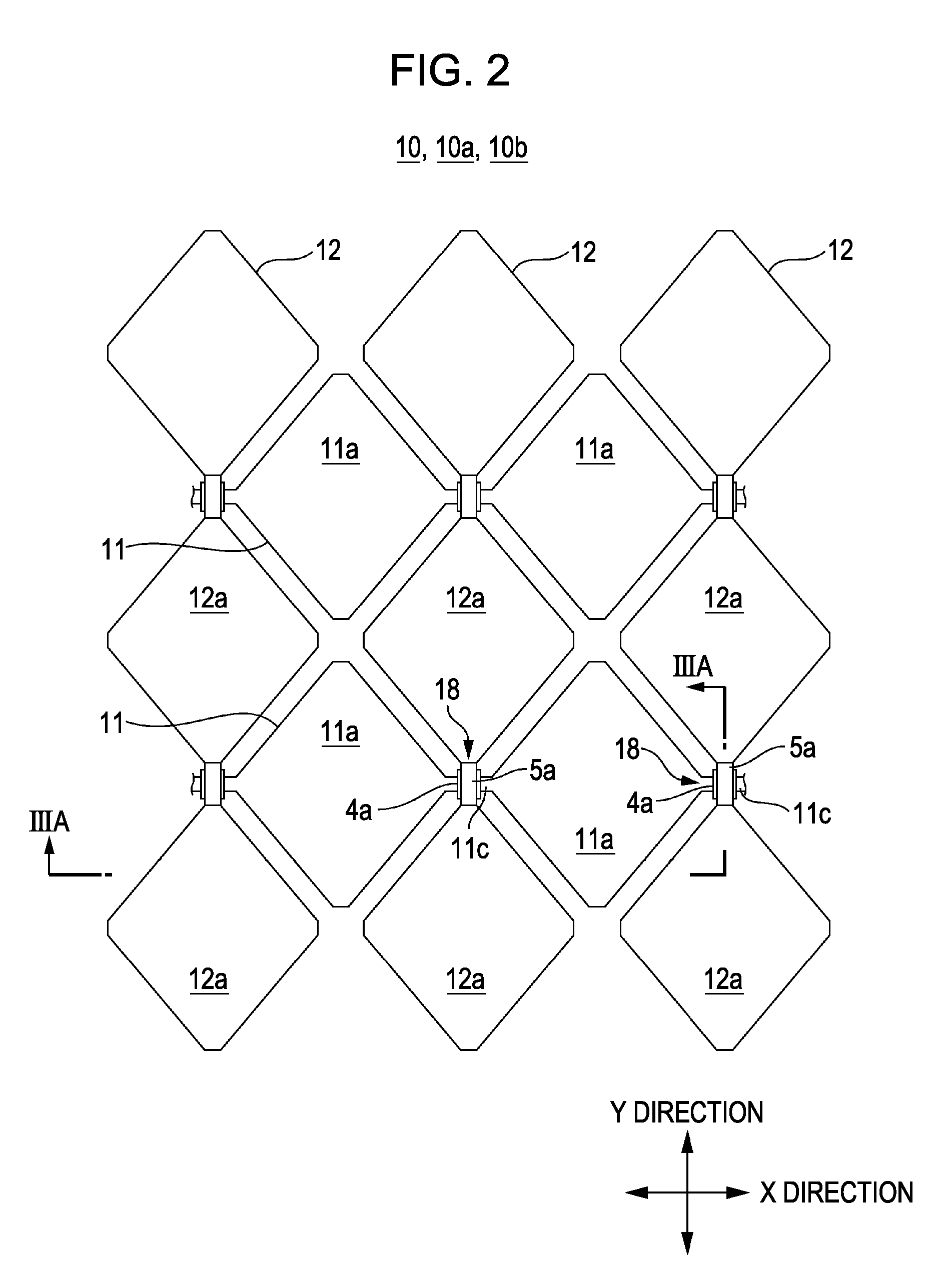
[0014]In the present invention, it is preferred that the first light-transmitting electrodes and the second light-transmitting electrodes are formed on the multilayer film with the same configuration using the same material, and at each of the intersections between the first light-transmitting electrodes and the second light-transmitting electrodes, either the first or second light-transmitting electrodes are continuous, while the other electrodes are discontinuous. Also, it is preferred that a light-transmitting interlayer insulation film is formed on the light-transmitting electrodes continuous at each of the intersections, and a light-transmitting
relay electrode is formed on the interlayer insulation film in order to electrically connect the other light-transmitting electrodes discontinuous at each intersection. In this configuration, the first and second light-transmitting electrodes may be formed by the same process because these electrodes have the same configuration, thereby simplifying the manufacturing process. In addition, when the first and second light-transmitting electrodes are formed between different
layers, the
film structure at each intersection is different from that of the first and second light-transmitting electrodes, and thus the intersections become noticeable even if the light-transmitting electrodes are formed so as to decrease a difference in reflectance between the region where the light-transmitting electrodes are formed and the region where the light-transmitting electrodes are not formed, in order to make the electrodes unnoticeable. In the present invention, the electrodes discontinuous at each intersection are electrically connected by the light-transmitting
relay electrode formed on the light-transmitting interlayer insulation film. Therefore, the area occupied by the intersections is narrow. In addition, the intersections are composed of a laminate of light-transmitting thin films and are thus made unnoticeable. As a result, in the present invention, the intersections are unnoticeable when viewed from the input surface side of the input device, and thus a high-quality image may be displayed when an image forming device is disposed at the back of the input device.
[0015]In the present invention, it is preferred that the multilayer film is formed over the entire input region including the region where the first light-transmitting electrodes and the second light-transmitting electrodes are not formed. In this configuration, patterning of the first light-transmitting electrodes and the second light-transmitting electrodes is easily efficiently performed, thereby simplifying the manufacturing process.
[0017]In this case, preferably, the
niobium oxide film has a thickness of 4 nm to 6 nm and a refractive index of 2.22 to 2.37, the
silicon oxide film has a thickness of 52 nm to 60 nm or 70 nm to 78 nm and a refractive index of 1.425 to 1.49, and the ITO film has a thickness of 17 nm to 23 nm and a refractive index of 1.87 to 1.945. In this configuration, the first light-transmitting electrodes and the second light-transmitting electrodes are composed of an ITO thick film, and thus the resistance of the light-transmitting electrodes is decreased.

