Relief printing plate precursor for laser engraving, relief printing plate, and method of manufacturing relief printing plate

a printing plate and laser engraving technology, applied in the field of laser engraving relief printing plate precursors, and relief printing plate manufacturing methods, can solve the problems of deterioration in printing durability, plate making process requires time and cost for the production of original image films, and relief layer has poor resistance to hydrophobic inks such as ultraviolet inks, etc., to achieve good water resistance, poor resistance to hydrophobic inks, and good water resistan

Inactive Publication Date: 2009-10-01
FUJIFILM CORP
View PDF27 Cites 7 Cited by
  • Summary
  • Abstract
  • Description
  • Claims
  • Application Information

AI Technical Summary

Benefits of technology

[0012]When a hydrophobic elastomer (rubber) is used as a binder polymer in a relief forming layer, a relief layer formed from such a relief forming layer has good water resistance and, therefore, is highly resistant to aqueous inks during printing. However, such a relief layer has poor resistance to hydrophobic inks such as a UV ink. Accordingly, printing using a printing plate having such a relief layer with a hydrophobic ink may cause elution of components from the relief layer during printing, which amounts to deficient strength of the printing plate, causing deterioration in printing durability.
[0013]On the other hand, when a hydrophilic binder such as a polyvinyl alcohol derivative is used, a relief layer formed from such a relief forming layer is highly resistant to hydrophobic inks, but has very poor resistance to water. Therefore, printing using a printing plate having such a relief layer with an aqueous ink may cause elution of components from the relief layer during printing and, therefore, practical printing durability is not achieved.
[0014]As is understood from the above, a relief forming layer incorporating a commonly-used binder polymer and which is suitable for both aqueous inks and UV inks as well as exhibiting good engraving sensitivity suitable for direct engraving CTP has not yet been provided.
[0015]In recent years, relief printing plates suitable for hydrophobic inks and containing ester solvents have been studied, and compositions containing hydrophobic elastomers have been proposed (for example, see JP-A No. 2007-148322). However, such elastomers have a low glass transition temperature, and are in the form of a rubber at normal temperature. Therefore, infrared laser exposure and heat generated by a photothermal conversion agent upon exposure can be used up in amplification of vibration of molecules, which lowers the energy efficiency of the thermal decomposition of the polymer. As a result of this, sufficient engraving sensitivity cannot be achieved.
[0016]As described above, various techniques have been proposed with respect to a relief forming layer of a relief printing plate precursor for laser engraving, but a relief printing plate precursor which provides both high sensitivity when subjected to laser engraving and suitability for both aqueous inks and hydrophobic inks such as a UV ink has not yet been provided.
[0017]The present invention has been achieved by taking the above circumstances into consideration. The present invention provides a relief printing plate precursor for laser engraving which reveals high engraving sensitivity when subjected to laser engraving and provides a printing plate suitably used for printing with an aqueous ink as well as for printing with a hydrophobic ink.

Problems solved by technology

In the case of producing a relief printing plate by analogue plate making, since an original image film using a silver salt material is needed in general, the plate making process requires time and costs for the production of original image films.
However, such a relief layer has poor resistance to hydrophobic inks such as a UV ink.
Accordingly, printing using a printing plate having such a relief layer with a hydrophobic ink may cause elution of components from the relief layer during printing, which amounts to deficient strength of the printing plate, causing deterioration in printing durability.
On the other hand, when a hydrophilic binder such as a polyvinyl alcohol derivative is used, a relief layer formed from such a relief forming layer is highly resistant to hydrophobic inks, but has very poor resistance to water.
Therefore, printing using a printing plate having such a relief layer with an aqueous ink may cause elution of components from the relief layer during printing and, therefore, practical printing durability is not achieved.
Therefore, infrared laser exposure and heat generated by a photothermal conversion agent upon exposure can be used up in amplification of vibration of molecules, which lowers the energy efficiency of the thermal decomposition of the polymer.
As a result of this, sufficient engraving sensitivity cannot be achieved.
As described above, various techniques have been proposed with respect to a relief forming layer of a relief printing plate precursor for laser engraving, but a relief printing plate precursor which provides both high sensitivity when subjected to laser engraving and suitability for both aqueous inks and hydrophobic inks such as a UV ink has not yet been provided.

Method used


Image

  • Relief printing plate precursor for laser engraving, relief printing plate, and method of manufacturing relief printing plate
  • Relief printing plate precursor for laser engraving, relief printing plate, and method of manufacturing relief printing plate
  • Relief printing plate precursor for laser engraving, relief printing plate, and method of manufacturing relief printing plate

Examples


example 1

[0446]1. Preparation of Crosslinkable Resin Composition for Laser Engraving

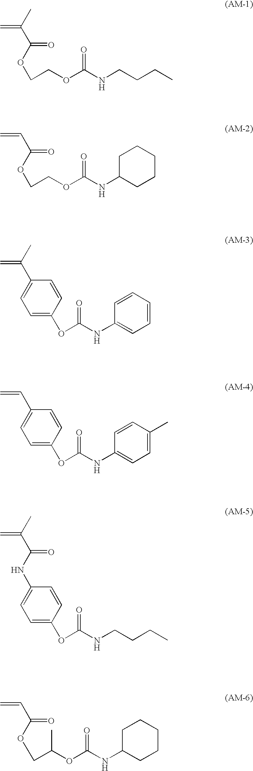
[0447]In a three necked flask equipped with a stirring blade and a cooling tube, 50 parts by mass of polyvinylbutyral (trade name: BL-1, manufactured by Sekisui Chemical Co., Ltd., Mw: 19,000) as the specific polymer (A), 1 part by mass of carbon black (trade name: KETJEN BLACK EC60OJD, manufactured by Lion Corporation) as the photo-thermal conversion agent (E), 20 parts by mass of diethylene glycol as the plasticizer, and 47 parts by mass of ethanol as the solvent were charged and heated while stirring at 70° C. for 120 min to dissolve the specific polymer (A). Further, the resultant was cooled 40° C., and added with 15 parts by mass of an ethylenically unsaturated monomer M-1 having a chemical structure shown below, 13 parts by mass of hydroxyethyl (meth)acrylate (trade name; BLEMMER PME200, manufactured by NOF Corp.), and 1 part by mass of t-butyloxybenzoate (trade name: PERBUTYL Z, manufactured by NOF Cor...


PUM

PropertyMeasurementUnit
glass transition temperatureaaaaaaaaaa
wavelengthaaaaaaaaaa

Abstract

The invention provides a relief printing plate precursor for laser engraving, comprising a relief forming layer, the relief forming layer comprising a resin composition for laser engraving, and the resin composition for laser engraving comprising a binder polymer (A) that is insoluble in water and soluble in an alcohol having 1 to 4 carbon atoms. The invention further provides a method for manufacturing a relief printing plate having crosslinking components of the relief forming layer and laser engraving the relief forming layer, and a relief printing plate formed thereby.

Description

CROSS-REFERENCE TO RELATED APPLICATIONS[0001]This application claims priorities under 35 USC 119 from Japanese Patent Application (JP-A) No. 2008-092990 filed on Mar. 31, 2008, and JP-A No. 2008-226319 filed on Sep. 3, 2008, the disclosures of which are incorporated by reference herein.BACKGROUND OF THE INVENTION[0002]1. Technical Field[0003]The present invention relates to a relief printing plate precursor for laser engraving, a relief printing plate, and a method of manufacturing a relief printing plate.[0004]2. Description of the Related Art[0005]As a method for forming a printing plate by forming a concave-convex structure on a photosensitive resin layer laminated over the surface of a support, a method of exposing a relief forming layer which has been formed using a photosensitive composition, to ultraviolet radiation through an original image film so as to selectively cure image areas, and removing uncured parts by means of a developer solution, that is, so-called “analogue pl...

Claims


Application Information

Patent Timeline
Patent Type & Authority Applications(United States)
IPC IPC(8): G03F7/004G03F7/20
CPCB41N1/12B41C1/05
Inventor SUGASAKI, ATSUSHIIMAI, MASAKO
Owner FUJIFILM CORP
Why Eureka
Try Eureka