

Radiation imaging apparatus and radiation imaging system
- Summary
- Abstract
- Description
- Claims
- Application Information
AI Technical Summary
Benefits of technology
Problems solved by technology
Method used
Image

Examples
first embodiment
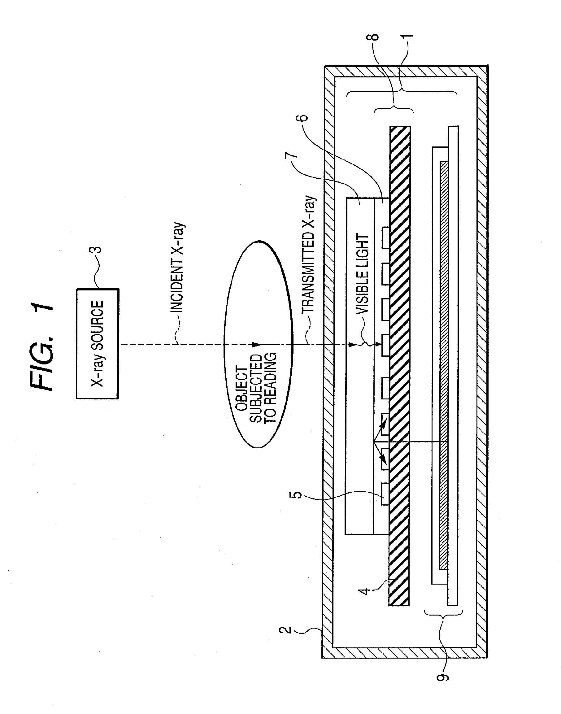
[0057]FIG. 1 is a schematic cross-sectional view of a radiation imaging apparatus according to a first embodiment of the present invention.
[0058]The radiation imaging apparatus 1 according to the present embodiment has the same configuration as the apparatus of the comparative example in FIG. 11 except that an EL (electroluminescence) light source 9 and a PIN photoelectric conversion element 105 are used to constitute an MIS photoelectric conversion element 5 in place of the LED light source 109.
[0059]FIG. 1 illustrates that the light from the EL light source 9 is vertically emitted to the scintillator 7, but an incident light from the diagonal direction also exists. Therefore, by including a specular reflection component over the scintillator surface, the scintillator will not absorb all light.
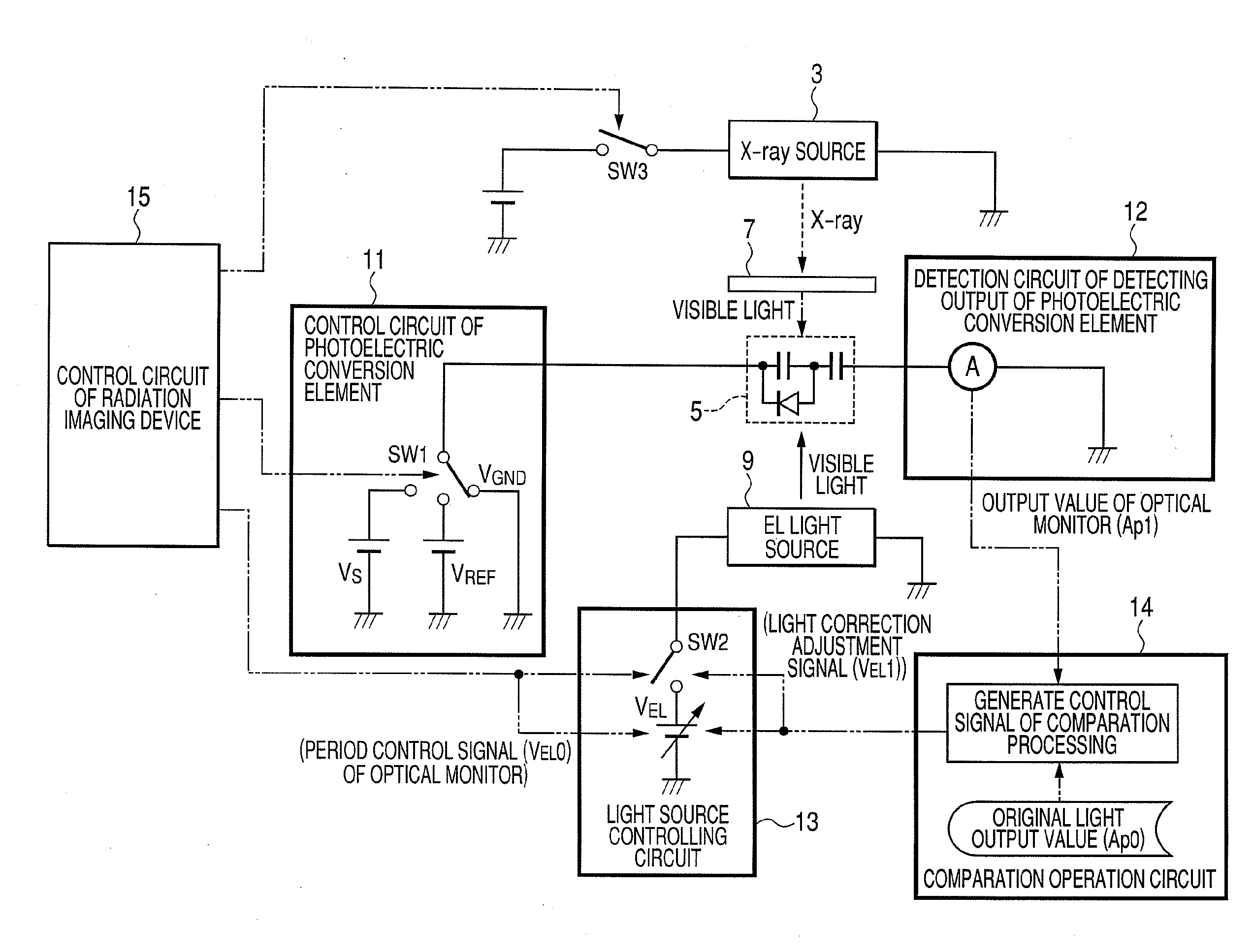
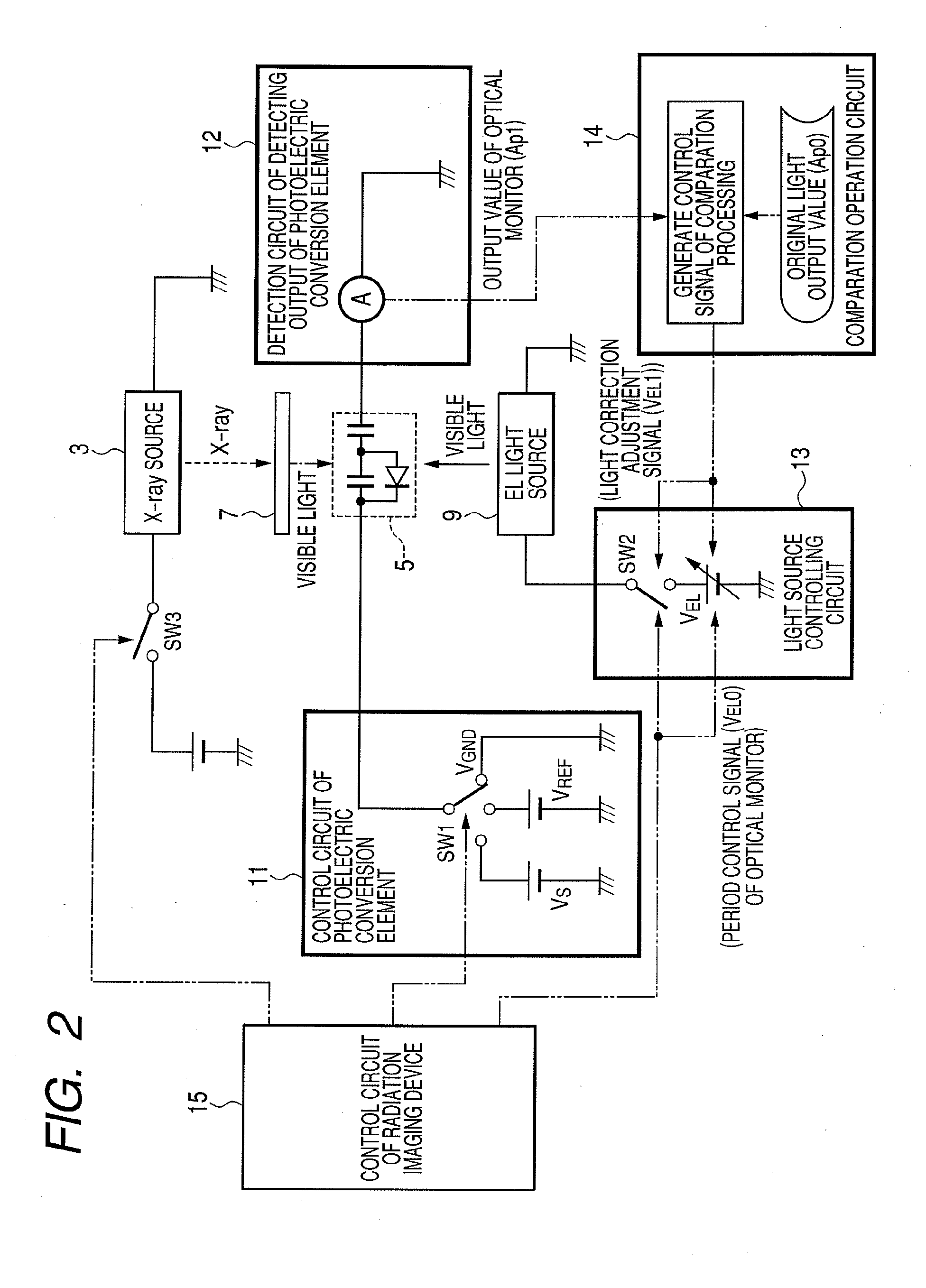
[0060]FIG. 2 is a circuit diagram of one pixel of a photoelectric conversion element in the radiation imaging apparatus according to the present embodiment.
[0061]In FIG. 2, the photoelectric ...
second embodiment
[0092]The present embodiment involves control of optical calibration for adjusting the length of a light emission period as well as the quantity of light irradiation to a photoelectric conversion element without the optical monitoring period present in the first embodiment.
[0093]Referring now to accompanying drawings, detailed description is made on the present embodiment.
[0094]A radiation imaging apparatus according to the present embodiment is the same as the apparatus in the first embodiment of FIG. 1.
[0095]FIG. 5 is a schematic circuit diagram of the radiation imaging apparatus according to the present embodiment.
[0096]FIG. 6 is an operational timing chart of a circuit in the radiation imaging apparatus according to the present embodiment.
[0097]FIG. 7 is a view illustrating a flow of optical calibration in the radiation imaging apparatus according to the present embodiment.
[0098]FIG. 8 is a graph illustrating an output of a photoelectric conversion element relative to the number...
third embodiment
[0108]The present embodiment is the same as the second embodiment and involves control of optical calibration for adjusting the length of light emission period as well as the quantity of light irradiation to a photoelectric conversion element without the optical monitoring period present in the first embodiment.
[0109]Referring now to accompanying drawings, detailed description is made on the present embodiment.
[0110]For the schematic circuit illustrated in FIG. 5, the operational timing illustrated in FIG. 6 and the flow of optical calibration illustrated in FIG. 7, which are illustrated in the second embodiment, the present embodiment has the same.
[0111]FIG. 9 is a graph illustrating a relationship between an output of an electric signal of a photoelectric conversion element and a quantity of light emission in the present invention.
[0112]In FIG. 9, the horizontal axis shows a quantity of light from the EL light source 9 and FIG. 9 illustrates that a quantity of incident light becom...
PUM
 Abstract
Description
Claims
Application Information