Motor drive device

a technology of motor drive and drive shaft, which is applied in the direction of electric devices, emergency protective arrangements for limiting excess voltage/current, transportation and packaging, etc., can solve the problems of inability to ensure a running distance reliably, increase current passing through the inverter, and large size of the inverter, so as to ensure motor safety and output performance, simple and inexpensive device structure, and high reliability of vehicles

Active Publication Date: 2009-10-08
TOYOTA JIDOSHA KK
View PDF19 Cites 75 Cited by
  • Summary
  • Abstract
  • Description
  • Claims
  • Application Information

AI Technical Summary

Benefits of technology

[0032]In the motor drive device described above, even when a switching element forming the driving circuit fails because of short-circuit, it is possible to continuously drive the three-phase AC motor simply by the existing device structure and to ensure running of the vehicle in the limp mode. As a result, a highly reliable vehicle can be realized in a simple and inexpensive manner.
[0033]According to the present invention, motor safety and output performance can be ensured when a malfunction of the inverter is detected, with a simple and inexpensive device structure. As a result, it is possible in the vehicle mounting the motor drive device in accordance with the present invention to maintain running performance in the limp mode and to attain higher reliability, in a simple and inexpensive manner.

Problems solved by technology

Therefore, when the motor speed is high, a current passing through the inverter may undesirably increase, as it receives high back electromotive force.
Therefore, it is difficult to secure a running distance to reliably move the vehicle to a safe area.
This inevitably leads to larger size of the inverter.
Further, it leads to increased cost of the device.
Therefore, as in the technique of Japanese Patent Laying-Open No. 2004-120883, it involves the problems of the size and cost of the device.
Other patent documents do not disclose any measure to control driving of a short-circuited inverter only by an existing device structure.

Method used


Image

  • Motor drive device
  • Motor drive device
  • Motor drive device

Examples


embodiment 1

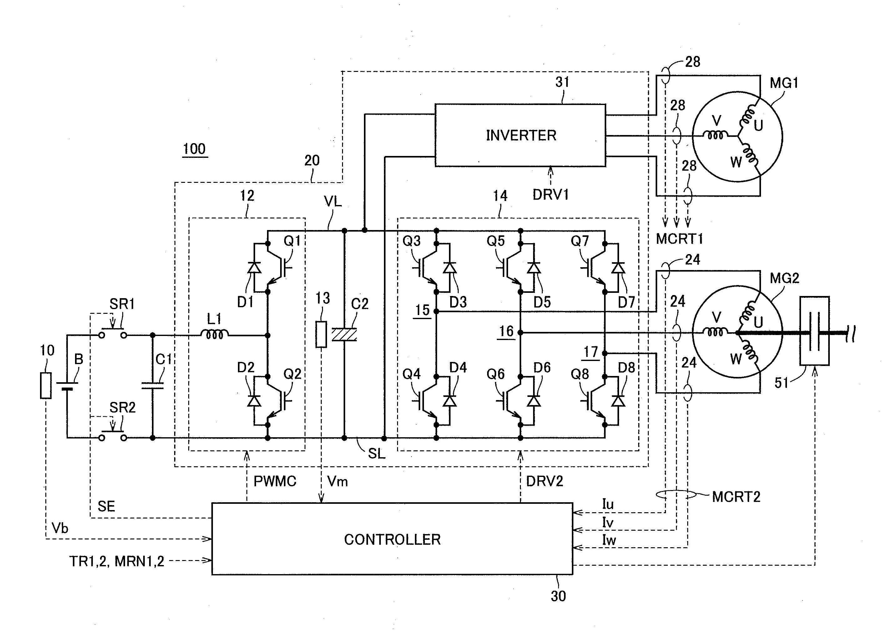
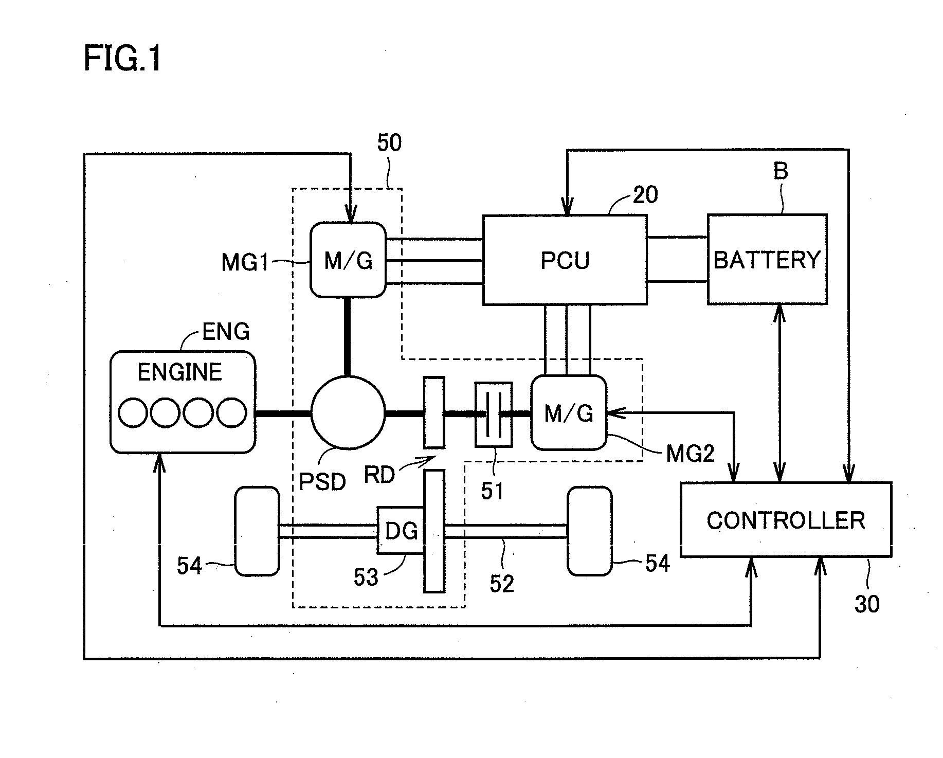
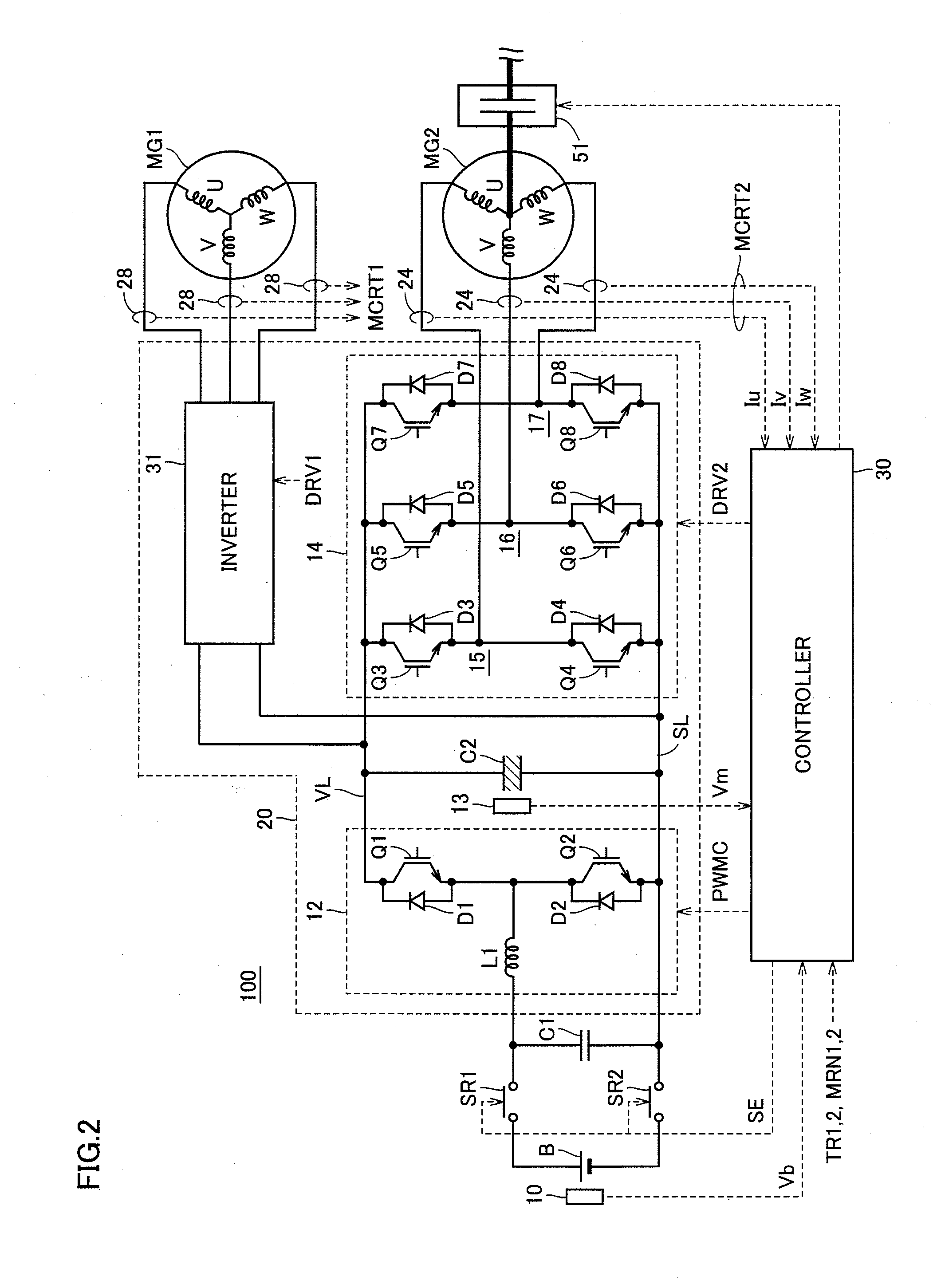
[0059]FIG. 1 is a block diagram showing a configuration related to motor generator control of the vehicle in accordance with Embodiment 1 of the present invention.

[0060]Referring to FIG. 1, the vehicle includes an engine ENG, a battery B, a trans axle 50, a power control unit (PCU) 20 controlling motor generators MG1 and MG2, a drive shaft 52, wheels 54, and a controller 30.

[0061]Engine ENG generates driving force using combustion energy of fuel such as gasoline as a source. Battery B supplies electric power to power control unit 20. Battery B is formed of a rechargeable secondary battery and, typically, a nickel hydride battery, a lithium ion battery, or a large capacity capacitor is used.

[0062]Trans axle 50 has a transmission and an axle as an integrated structure, and has a power split device PSD, a reduction device RD, a differential gear (DG) 53, motor generators MG1 and MG2, and a clutch 51.

[0063]Power control unit 20 converts the DC power supplied from battery B to AC power a...

embodiment 2

[0153]As to the method of identifying the short-circuited arm of inverter 14 as the first characteristic of the present invention, other than the method of identification based on the motor currents Iu, Iv and Iw of inverter 14, identification based on inter-phase voltage of motor generator, which will be described later, is also possible.

[0154]FIG. 13 is a schematic block diagram of motor drive device in accordance with Embodiment 2 of the present invention. Motor drive device 100A corresponds to motor drive device 100 of FIG. 1, additionally including voltage sensors 18 to 20 for detecting the inter-phase voltage of motor generator 2 and having a controller 30A in place of controller 30. Therefore, detailed descriptions of portions common to those of FIG. 1 will not be repeated.

[0155]Referring to FIG. 13, voltage sensor 18 detects an inter-phase voltage Vvu between the U-phase and V-phase of motor generator MG2, and outputs the detected inter-phase voltage Vvu to controller 30A. V...

embodiment 3

[0187]By the method of identifying the short-circuit portion in accordance with Embodiment 2 described above, it is possible to identify the short-circuited arm included not only in the single phase but also in each of the plurality of phases. Therefore, even when two of the three phases are short-circuited, it is possible to continuously drive motor generator MG2 while protecting inverter 14 from overheating, by causing switching operation of the remaining one normal phase, in the manner as will be described in the following.

[0188]In the following, drive control of motor generator MG2 after the detection of short-circuit of two phases will be described.

[0189]FIG. 22 illustrates the drive control of motor generator MG2.

[0190]FIG. 22 assumes that the upper arm of U-phase 15 (IGBT element Q3) and the upper arm of V-phase 16 (IGBT element Q5) are short-circuited.

[0191]Referring to FIG. 22, when the upper arms of U-phase 15 and V-phase 16 are both short-circuited, the lower arm of W-pha...


PUM


Abstract

When an upper arm of U-phase has failed because of short-circuit, lower arms of V-phase phase and W-phase as the opposite arms are switching-operated. When only the lower arm of V-phase is turned on, a route of motor current passing through an IGBT element from a V-phase coil is formed, and therefore, the motor current returning to the short-circuited phase decreases. Further, by the switching operation of the arm opposite to the short-circuited arm, an AC current is induced in a motor generator. Therefore, it is possible to continuously drive the motor generator while preventing increase in the current passing through the short-circuited phase, without adding a new device structure. This ensures running of the vehicle in the limp mode.

Description

TECHNICAL FIELD[0001]The present invention relates to a motor drive device and, more specifically, to a motor drive device allowing continuous operation of the motor when a driving circuit controlling driving of the motor is failed by a short-circuit.BACKGROUND ART[0002]Recently, a hybrid vehicle and an electric vehicle are attracting attention as ecologically friendly vehicles. A hybrid vehicle has, as power sources, a DC power source, an inverter and a motor driven by the inverter, in addition to a conventional engine. Specifically, power is obtained by driving the engine and, in addition, the DC voltage from the DC power source is converted to AC voltage by the inverter, the motor is rotated by the converted AC voltage, and whereby power is obtained.[0003]An electric vehicle has a DC power source, an inverter and a motor driven by the inverter, as power sources.[0004]In a motor drive device mounted on a hybrid vehicle or an electric vehicle as such, typically, when a malfunction ...

Claims


Application Information

Patent Timeline
Patent Type & Authority Applications(United States)
IPC IPC(8): H02H9/02
CPCB60L3/003B60L9/18H02P29/022H02M7/53871H02P27/06H02M1/32H02P29/032
Inventor SHIBA, KENJIROTANAKA, TAKASHITANAKA, NOBUTAKA
Owner TOYOTA JIDOSHA KK
Why Eureka
Try Eureka