Check patentability & draft patents in minutes with Patsnap Eureka AI!

Laser oscillator and laser processing apparatus

Inactive Publication Date: 2009-10-08
MIYACHI TECHNOS CORP
View PDF4 Cites 3 Cited by
  • Summary
  • Abstract
  • Description
  • Claims
  • Application Information

AI Technical Summary

Benefits of technology

[0009]The present invention was conceived to solve the above problems of conventional techniques, and it is therefore the object of the present invention to provide a laser oscillator and a laser processing apparatus that achieve a further improvement in laser oscillation efficiency and higher output of a higher harmonic wave laser beam to enhance processing capability.
[0012]In the above configuration, the ¼ wavelength plate is disposed in the optical resonator. This stabilizes a power ratio between ordinary light and extraordinary light to the nonlinear optical crystal cut for type II 
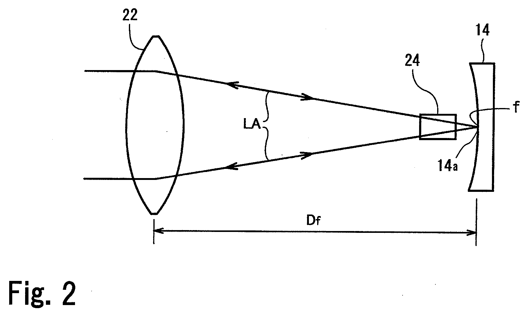
phase matching. The focus of the optical lens is determined to be near the reflection surface of the first terminating mirror, and the optical lens is disposed to be separated from the reflection surface of the first terminating mirror by the distant approximately equal to the focal distance across the nonlinear optical crystal. This optically couples the nonlinear optical crystal to a fundamental mode of the optical resonator while prevents the scattering loss of a light beam of a fundamental wavelength at the refection surface of the first terminating mirror, thus sufficiently confines the light beam of the fundamental wavelength in the optical resonator to improve the amplification factor of the fundamental wave and consequently improve laser conversion efficiency. In this manner, disposing the ¼ wavelength plate in the optical resonator and determining the focus of the optical lens to be near the refection surface of the first terminating mirror to strengthen the optical coupling between the fundamental mode and the nonlinear optical crystal bring about a synergistic effect, which enables the generation of a higher harmonic wave laser beam of output power far greater than a conventional higher harmonic wave laser beam.
[0014]According to a preferred aspect of the present invention, the focus of the optical lens is determined to be at a position separated from the reflection surface of the first terminating mirror toward the optical lens by a distance of 5 mm or less (more preferably, about 2 mm). In this manner, shifting the position of focus of the optical lens properly from the reflection surface of the first terminating mirror toward the optical lens surely prevents an undesired phenomenon that the energy of fundamental wave laser beam burns out the optical lens.
[0017]Having the laser oscillator of the present invention, the laser processing apparatus of the present invention greatly improves a capability of laser processing using a higher harmonic wave laser beam of high output power.
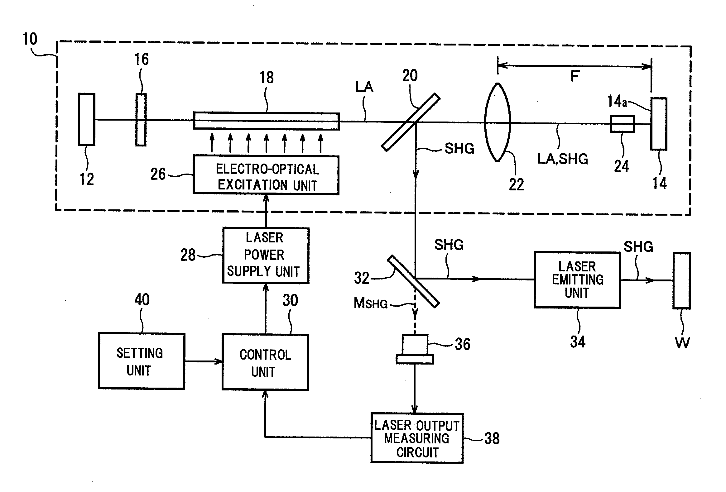
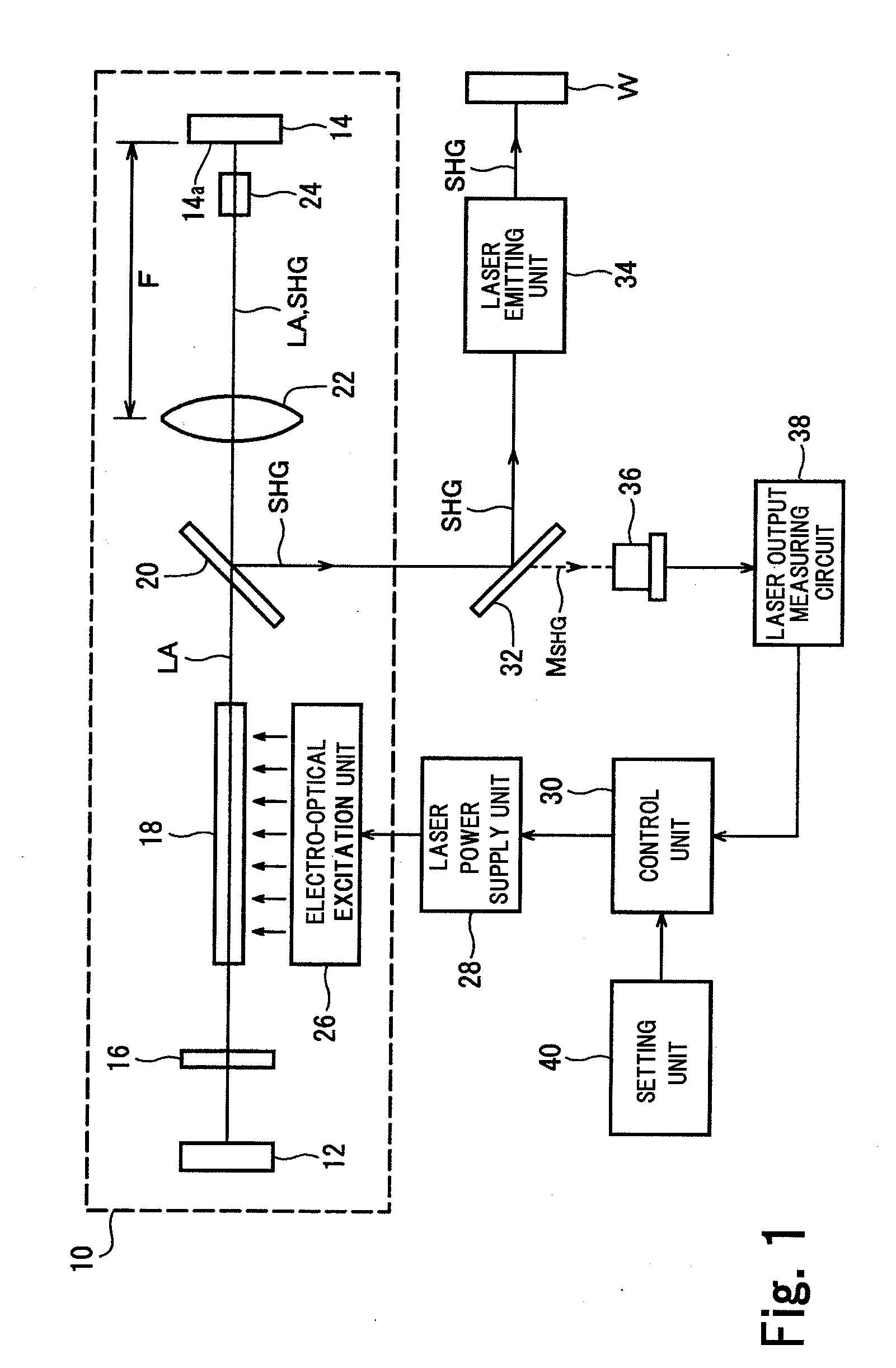
[0020]The laser processing apparatus may include a power feedback control mechanism that has a higher harmonic wave laser output measuring unit that measures the laser output of a higher harmonic wave laser beam, and a control unit that controls switching of the switching element to match a laser output measurement to a reference value or a reference waveform. In this case, as described above, the ¼ wavelength plate works to stabilize a phase difference between natural polarization waves (S wave and P wave) resulting from a beam of the fundamental wavelength and a power ratio between ordinary light and extraordinary light. This allows linear power feedback control, thus enables more stable and exact matching of the output of the higher harmonic wave laser beam to the reference value or the reference waveform.
[0021]According to the laser oscillator of the present invention, the above configurations and operations achieve a further improvement in laser oscillation efficiency and higher output of a higher harmonic wave laser beam. According to the laser processing apparatus of the present invention, the above configurations and operations improve the processing capability of a higher harmonic wave laser beam.

Problems solved by technology

Still, a problem remains in terms of laser output.
This destabilizes the output of a fundamental wave laser beam, and consequently destabilizes the output of a second higher harmonic wave laser beam.
This kind of laser output fluctuation is difficult to compensate even with the power feedback control mechanism because increasing laser output to compensate a decrease in laser output intensifies the influence of the thermal lens effect.

Method used


Image

  • Laser oscillator and laser processing apparatus
  • Laser oscillator and laser processing apparatus
  • Laser oscillator and laser processing apparatus

Examples


Embodiment Construction

[0028]A preferred embodiment of the present invention will now be described with reference to the accompanying drawings.

[0029]FIG. 1 depicts a configuration of a laser processing apparatus according to an embodiment of the present invention. This laser processing apparatus is configured as a green laser processor that performs desired laser processing (e.g., laser welding) on a workpiece W mainly made of copper or gold, using a green laser beam (second higher harmonic wave of 532 nm in wavelength) in the form of a long pulse (with a pulse width of 10 μs or higher, typically 1 to 3 ms).

[0030]A laser oscillator 10 of the laser processing apparatus includes a pair of terminating mirrors 12 and 14, between which a straight light path lies, and also includes a ¼ wavelength plate 16, an active medium 18, a higher harmonic wave separating / outputting mirror 20, a condensing lens 22, and a nonlinear optical crystal (wavelength converting crystal) 24 that are lined up from the left to right o...


PUM


Abstract

A laser oscillator of a laser processing apparatus includes a pair of terminating mirrors, between which a straight light path lies, and also includes a ¼ wavelength plate, an active medium, a higher harmonic wave separating / outputting mirror, a condensing lens, and a nonlinear optical crystal (wavelength converting crystal) that are lined up at given intervals on the light path between the terminating mirrors. The focus of the optical lens is determined to be near a reflection surface of the first terminating mirror, so that the optical lens is disposed to be separated from the reflection surface of the first terminating mirror by a distant approximately equal to a focal distance across the nonlinear optical crystal on the light path of an optical resonator.

Description

BACKGROUND OF THE INVENTION[0001]1. Field of the Invention[0002]The present invention relates generally to a laser processing apparatus that uses a higher harmonic wave laser beam for laser processing, and, more particularly, to a laser oscillator that generates a higher harmonic wave laser beam from a fundamental wave laser beam in an optical resonator and to a laser processing apparatus having the laser oscillator.[0003]2. Description of the Related Art[0004]Processing using higher harmonic wave laser having a frequency N times (N denotes an integer equal to or more than 2) the frequency of a YAG fundamental wave has been garnering attention in these days. For example, visible light laser (green laser) of a second higher harmonic wave having a wavelength half (532 nm) of that of the YAG fundamental wave (1064 nm) has come into wide use for processing metals, such as copper and gold. A YAG second higher harmonic wave laser beam shows a fine absorption rate to copper and gold, thus ...

Claims


Application Information

Patent Timeline
IPC IPC(8): H01S3/10G02F1/37H01S3/00H01S3/131
CPCH01S3/08H01S3/08054H01S3/08072H01S3/094076H01S3/1312H01S3/109H01S3/1305H01S3/1306H01S3/1024
Inventor KASE, JUNPEIAMANO, SATORU
Owner MIYACHI TECHNOS CORP
Features
  • R&D
  • Intellectual Property
  • Life Sciences
  • Materials
  • Tech Scout
  • Unparalleled Data Quality
  • Higher Quality Content
  • 60% Fewer Hallucinations
Learn More