Active matrix substrate, reflection type liquid crystal display apparatus and liquid crystal projector system

Inactive Publication Date: 2009-10-22
CANON KK
View PDF6 Cites 11 Cited by
  • Summary
  • Abstract
  • Description
  • Claims
  • Application Information

AI Technical Summary

Benefits of technology

[0006]However, the techniques disclosed in the literatures described above cannot satisfy the requirements about the flatness of the reflection type liquid crystal display apparatus. The technique disclosed in the Japanese Patent Application Laid-Open No. 2006-267937 can improve the flatness of layers above the reflection electrodes but cannot improve the flatness of layers below the reflection electrodes. Thus, when the flatness of a layer below the reflection electrodes decreases, the flatness of the reflection electrodes and layers above the reflection electrodes also decreases. According to the U.S. Pat. No. 5,990,988, the dummy pattern of the wiring layer serves to reduce the pattern nonuniformity of the wiring layer to reduce the effect of the pattern nonuniformity of the wiring layer o

Problems solved by technology

However, the techniques disclosed in the literatures described above cannot satisfy the requirements about the flatness of the reflection type liquid crystal display apparatus.
The technique disclosed in the Japanese Patent Application Laid-Open No. 2006-267937 can improve the flatness of

Method used


Image

  • Active matrix substrate, reflection type liquid crystal display apparatus and liquid crystal projector system
  • Active matrix substrate, reflection type liquid crystal display apparatus and liquid crystal projector system
  • Active matrix substrate, reflection type liquid crystal display apparatus and liquid crystal projector system

Examples


first embodiment

[0021]With reference to FIGS. 1 to 5, an active matrix substrate and a reflection type liquid crystal display apparatus according to a first embodiment of the present invention will be described in detail. First, referring to FIG. 3, an exemplary circuit of the reflection type liquid crystal display apparatus will be described. FIG. 3 is a schematic equivalent circuit diagram illustrating the reflection type liquid crystal display apparatus according to the first embodiment of the present invention. Note that, in FIG. 3, illustration of pixels for providing only black display is omitted.

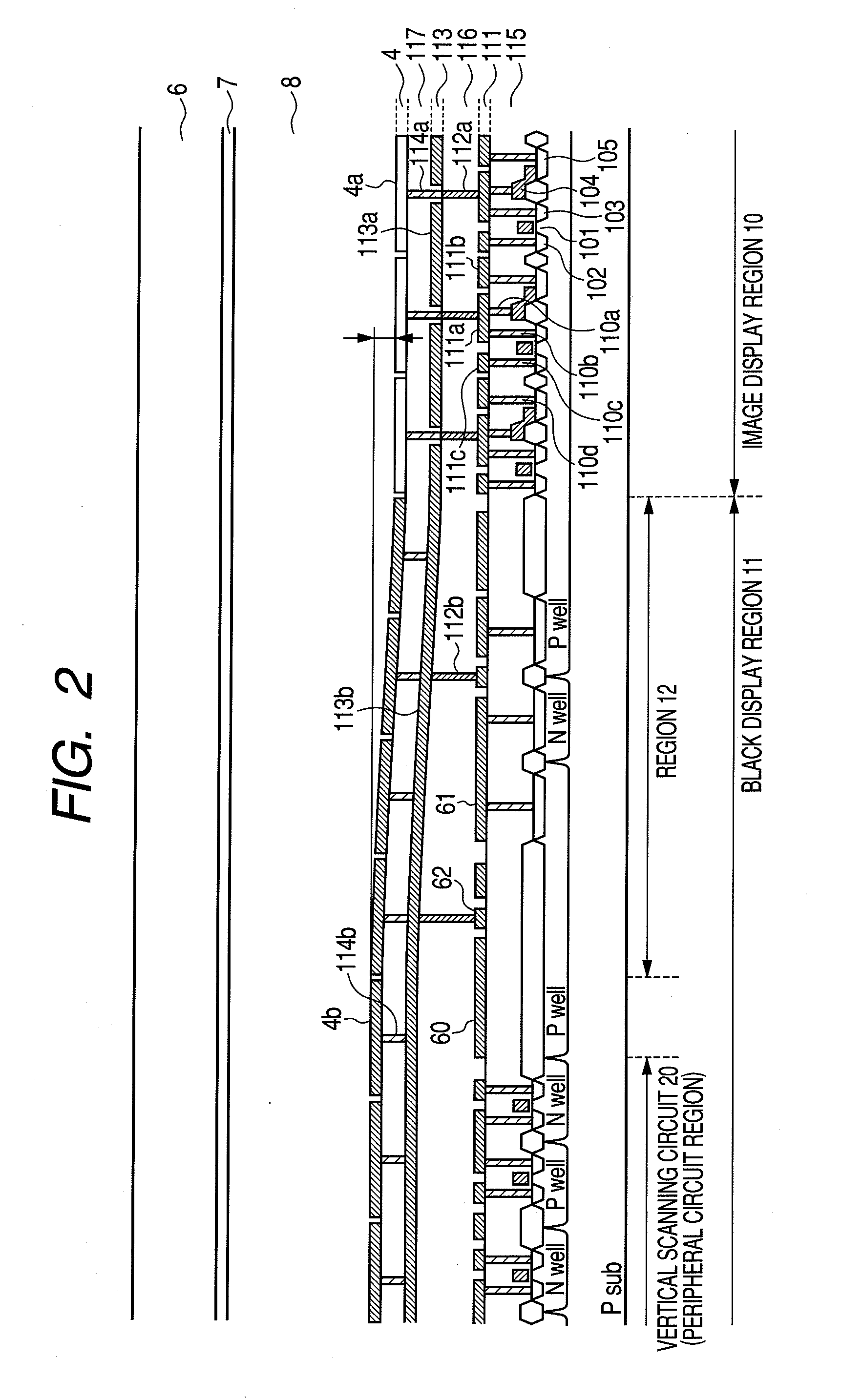
[0022]An image display region 10 has a matrix array of a plurality of pixels 1 for displaying an image (which correspond to first pixels according to the present invention) formed on a substrate. Each pixel 1 has a switching element 2, a holding capacitor 3 and a reflection electrode 4a. The switching element 2 is a MOS transistor formed on a single-crystal semiconductor substrate, for example, and h...

second embodiment

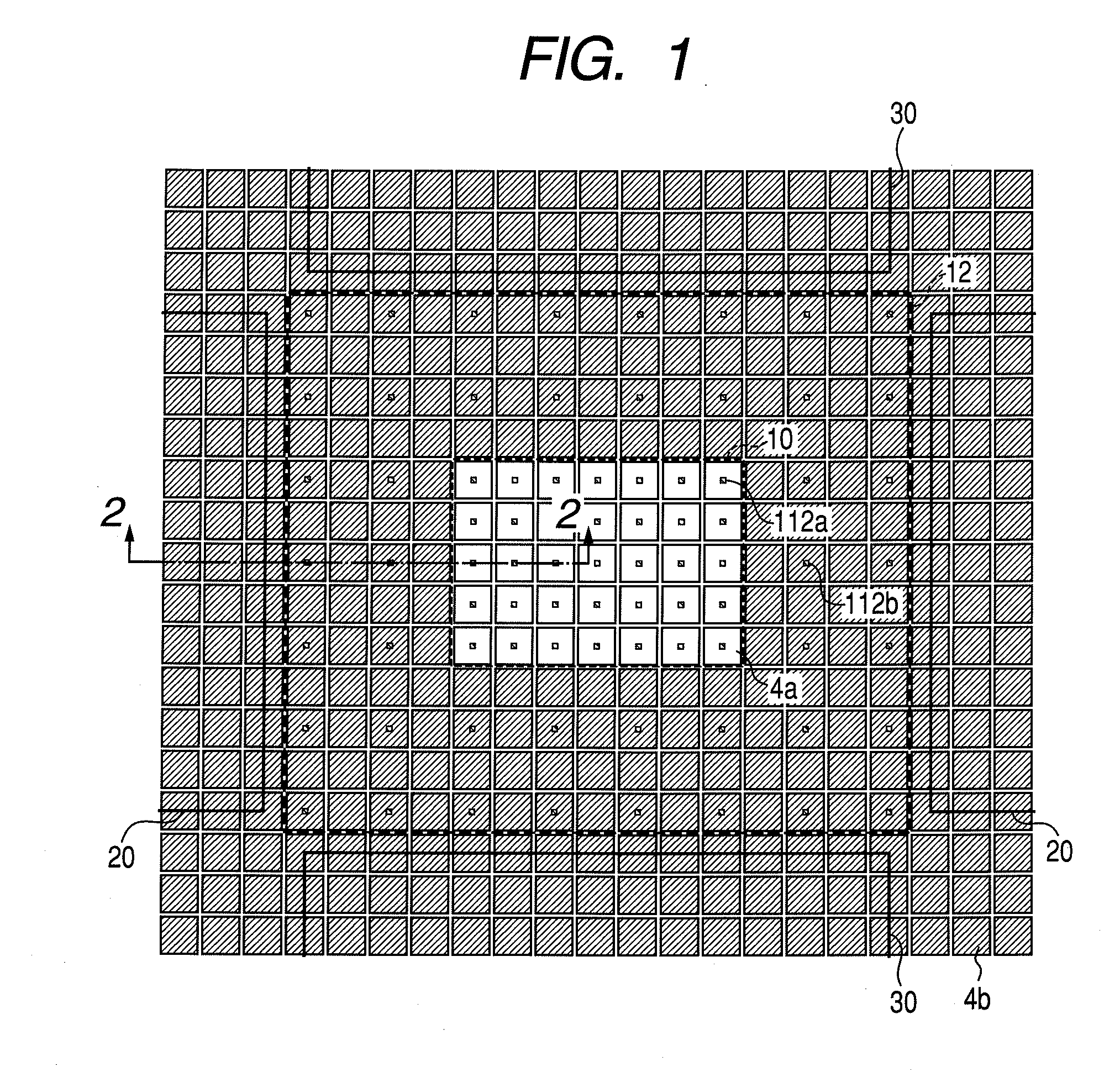
[0048]Next, referring to FIG. 6, a second embodiment of the present invention will be described in detail. FIG. 6 is a schematic plan view of a projection region of an active matrix substrate for use in a reflection type liquid crystal display apparatus according to the second embodiment of the present invention. The same components as those in the first embodiment are denoted by the same reference numerals, and descriptions thereof will be omitted.

[0049]The second embodiment differs from the first embodiment in that the density of the second through holes 112b in the region 12 is gradually reduced from the image display region 10 to the peripheral circuit region. That is, in the second embodiment, a plurality of second through holes 112b is disposed so that the density thereof in the black display region 11 is gradually reduced toward the outer edge of the black display region 11. The remainder of the arrangement is the same as that in the first embodiment, and descriptions thereof...

third embodiment

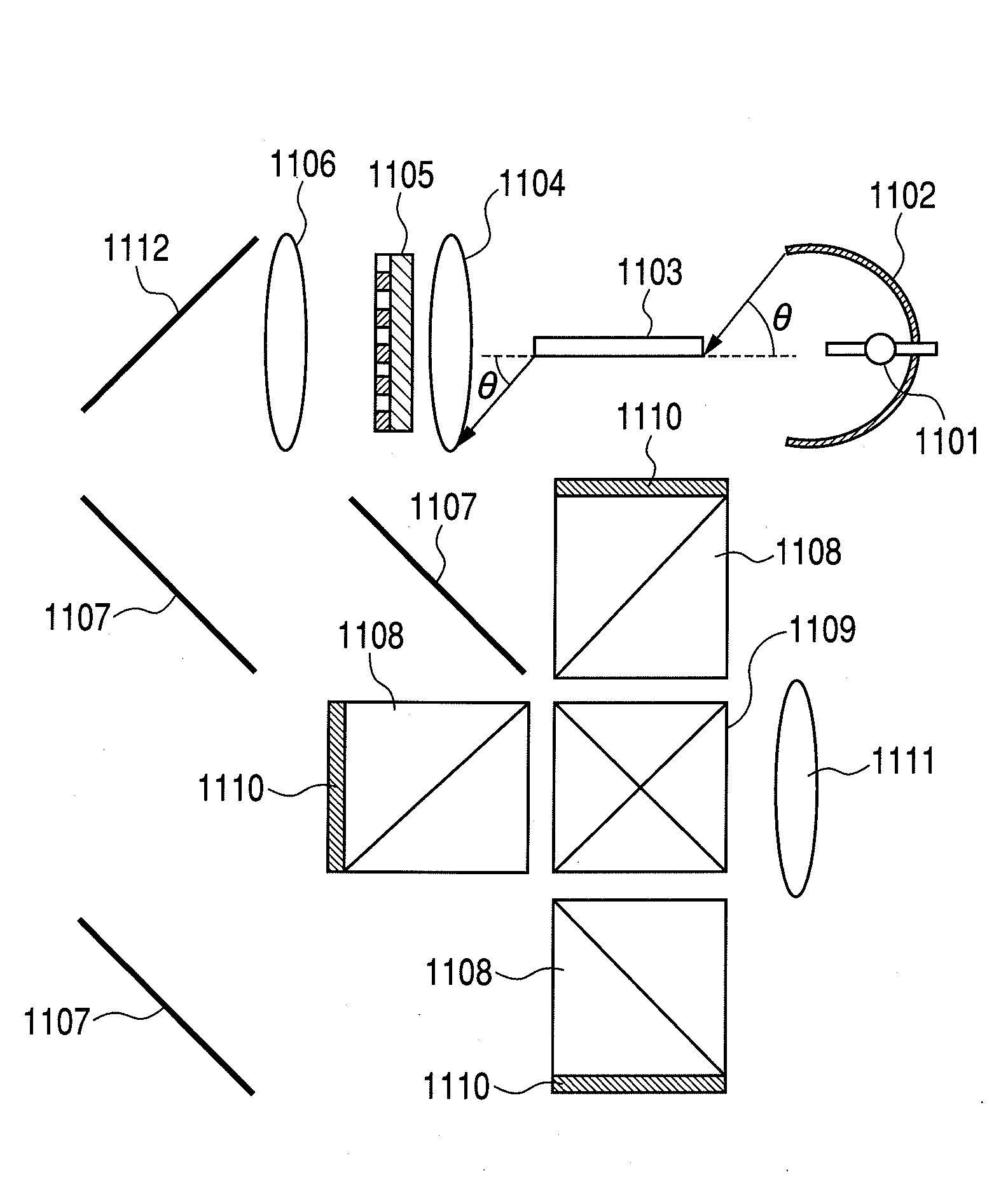
[0051]Next, a liquid crystal projector system using a reflection type liquid crystal display apparatus incorporating an active matrix substrate according to the present invention will be described. FIG. 7 is a conceptual view of an example of a liquid crystal projector system according to the present invention.

[0052]FIG. 7 shows a lamp 1101, a reflector 1102, a rod integrator 1103, a collimator lens 1104, a polarization converter system 1105, a relay lens 1106 and a dichroic mirror 1107. FIG. 7 further shows a polarization beam splitter 1108, a cross prism 1109, a reflection type liquid crystal panel 1110 incorporating an active matrix substrate according to the present invention, a projection lens 1111 and a total reflection mirror 1112.

[0053]A light flux emitted from the lamp 1101 is reflected by the reflector 1102 and collected at the input end of the integrator 1103. The reflector 1102 is an ellipsoidal reflector that has focuses at the point of light emission and the input end ...


PUM


Abstract

An active matrix substrate for a reflection type liquid crystal display apparatus has an image display region 10 including a plurality of pixels 1 each having a reflection electrode 4a and a switching element 2, a black display region 11 including a plurality of pixels for providing only a black display each having a reflection electrode 4b, a wiring layer 111 between the switching elements 2 and the reflection electrodes, a light shielding layer 113 between the wiring layer 111 and the layer forming the reflection electrodes, a through hole 112a between the wiring layer 111 and the light shielding layer 113 in the image display region 10 for electrically connecting the reflection electrode 4a to the switching element 2, and a through hole 112b between the wiring layer 111 and the light shielding layer 113 in the black display region 11 and electrically isolated from the switching element 2.

Description

BACKGROUND OF THE INVENTION[0001]1. Field of the Invention[0002]The present invention relates to an active matrix substrate including a matrix array of a plurality of pixels having a reflection electrode formed on a substrate, a reflection type liquid crystal display apparatus and liquid crystal projector system using the same.[0003]2. Description of the Related Art[0004]The reflection type liquid crystal display apparatus is a known image display apparatus using an active matrix substrate and is widely used in liquid crystal projectors and reflection type liquid crystal displays (referred to as liquid crystal projector systems hereinafter), for example. The active matrix substrate used in the reflection type liquid crystal display apparatus has a matrix array of a plurality of pixels formed on a semiconductor substrate, such as a single-crystal silicon substrate, each of the pixels including a switching element and a pixel electrode having a reflective characteristic (referred to a...

Claims


Application Information

Patent Timeline
IPC IPC(8): G02F1/1335
CPCG02B27/1026G02F1/133553G02F1/13454G09G2320/0238G02F2001/133388G09G3/002G09G3/3611G02F1/136277G02F1/133388
Inventor KAMEYAMA, HIROAKIOOMURA, MASANOBU
Owner CANON KK
Why Eureka
Try Eureka