Digital imaging system and method using multiple digital image sensors to produce large high-resolution gapless mosaic images

a digital imaging and mosaic image technology, applied in the field of digital imaging systems, can solve the problems of pixel-count sensors, difficult to readout, and custom-built low-yield focal plane arrays (fpas) which due to custom fabrication are often prohibitively expensive, and achieve the effects of large images, difficult production, and difficult readou

Inactive Publication Date: 2009-10-29
LAWRENCE LIVERMORE NAT SECURITY LLC
View PDF10 Cites 374 Cited by
  • Summary
  • Abstract
  • Description
  • Claims
  • Application Information

AI Technical Summary

Benefits of technology

[0027]Another advantage of the invention is the ability to produce larger images with existing COTS sensors. Large monolithic sensors are expensive, difficult to produce and very difficult to readout in a reasonable time frame—shorter than the inner frame time needed by the sensor system. An array of smaller sensors, with smaller pixel counts can be connected to an image collection system made up of many smaller, less expensive processors. The time needed to “clock” out or read an entire image from a gigapixel camera, using a monolithic sensor, would be much longer than the time to read out the 96 smaller sensors as shown in my plots.
[0028]Customizable sensor configuration for imaging odd-shaped target regions—It is also applicable to produce images of arbitrary size, aspect ratio and pixel count in the horizontal and vertical axes of the composite image. This can produce a sensor that can have non-rectangular shapes as well. If a cross roads or intersection were needed to be recorded at high spatial resolution, an arrangement of sensors in a “T” shape could be formed behind the lens / sensor sets and only record those areas of interest. This can be done with current larger sensors by throwing away the wanted data, but for some sensor types you still need to readout the entire array before you parse out the required pixels. For even odder shaped applications, such as the inspection of industrial process at high resolution, an arrangement of sensors could be envisioned that could just look at the center and corners and other selected regions of the image field at one time. Again it is the ability to optically multiplex many smaller sensors together to form a higher pixel count final “image” than is currently available.
[0029]The digital imaging system and method of the present invention is not limited to visible light imaging system applications, but also can be applied to infrared, ultraviolet, microwave or x-ray imaging regimes. Any imaging or sensor application where the pixel count needed exceeds those of a single sensor can employ this technology. Thus while this method of optically stitching images together is primarily designed for aerial remote sensing from high altitude air transport platforms, but could be used for other imaging modalities such as astronomy, x-ray radiography, transmission electron microscopy, x-ray imaging for computer-assisted tomography or other areas where the current pixel count of available sensors is inadequate to meet the requirements of the project. This method could be used for aerial surveillance for Homeland Defense, national Defense and Department of Defense applications. It also has utility in the collection of images from high altitude balloon-based sensors for weather, navigation, pollution sensing or military and geopolitical applications. And other applications may include the recording of high pixel count, high spatial resolution, images of flat or 3 dimensional works of art, historical documents or equipment or imagery used for remote sensing of agriculture, urban planning or GIS / mapping applications. Generally, the technique has application in a number of other areas where an “Image” or “Image-like” representation of scene or depiction of a spatially varying 2D output from a variety of detectors. While the present invention may be ideally used in aerial photographic applications it may be used in any application where the number of pixels desired from the area or region of interest exceed current detector technology pixel count. The method of multiplexing detectors in a checkerboard array, with 4 lenses is used to allow a contiguous coverage on the object plane to be mapped onto multiple detectors in the image plane. The apparatus and method of the present invention can be applied to more than just aerial photographic applications. For example, it is also applicable to other areas of “Imaging” such as IR, UV, microwave, radar, thermal, ultrasonic and x-ray imaging systems. And the present invention is preferably used for such imaging applications as aerial photography, cartography, photogrammetry, remote sensing are potential uses for this system.

Problems solved by technology

However, since such large pixel-count sensors are not currently commercially available i.e. the current state of the art in pixilated sensors is much less than the imaging requirement for such large area imaging applications, alternative imaging systems and methods of producing such large pixel-count images are required.
One technique uses custom built low yield large pixel-count focal plane arrays (FPAs) which due to their custom fabrication are often prohibitively expensive.
While also being costly, however, these types of buttable FPAs are often problematic with respect to their imaging performance caused by gaps in the image where image data is lost.
As such, these known limitations have generally inhibited widespread adoption and use for large area imaging applications.

Method used


Image

  • Digital imaging system and method using multiple digital image sensors to produce large high-resolution gapless mosaic images
  • Digital imaging system and method using multiple digital image sensors to produce large high-resolution gapless mosaic images
  • Digital imaging system and method using multiple digital image sensors to produce large high-resolution gapless mosaic images

Examples


Embodiment Construction

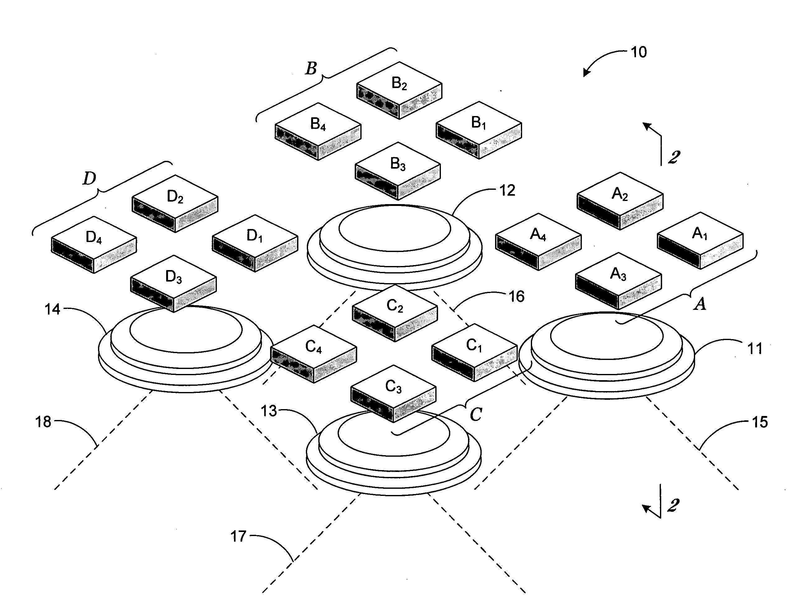
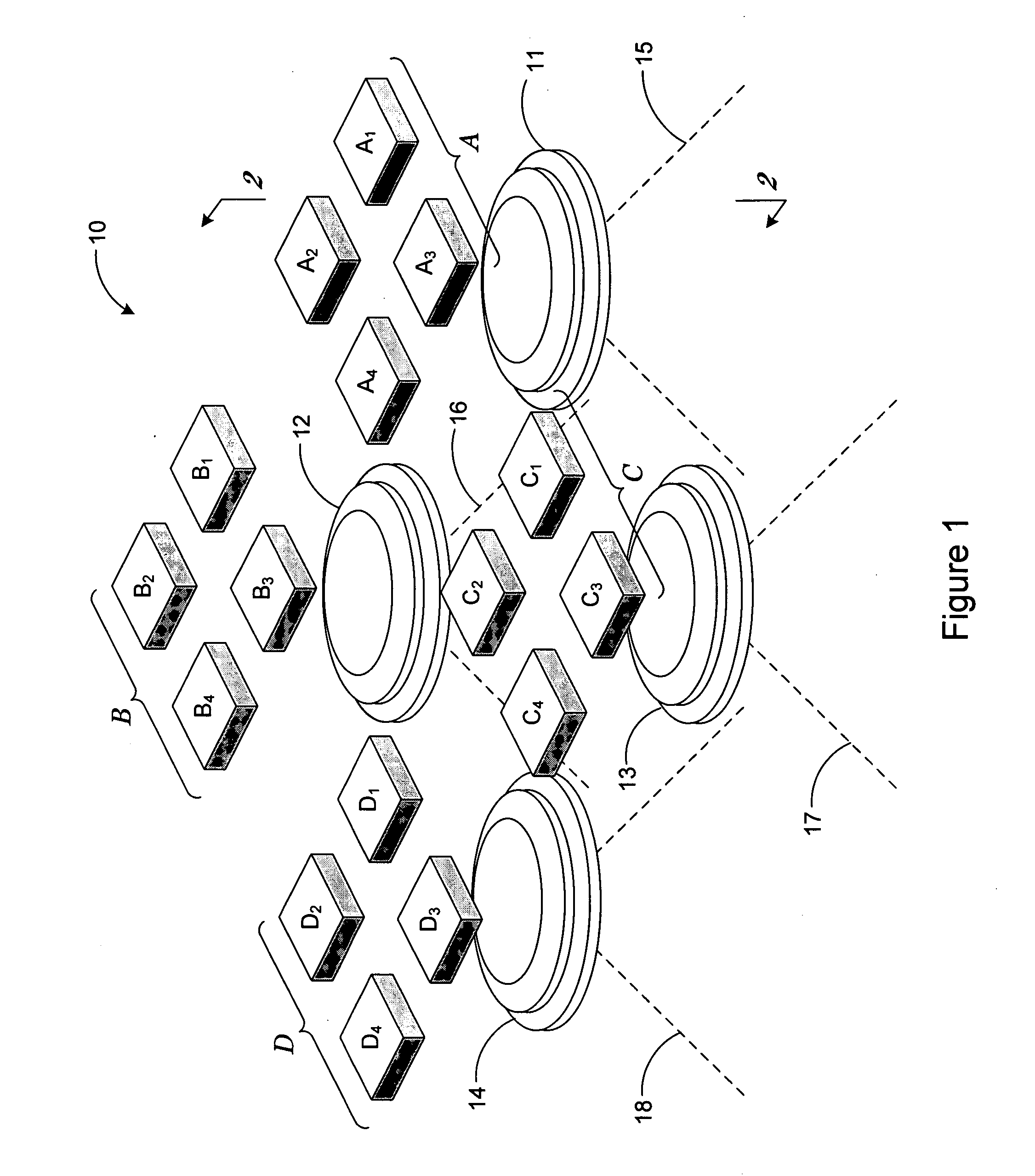
[0053]Turning now to the drawings, FIGS. 1-12 show a first exemplary embodiment of the digital imaging system of the present invention, generally indicated at reference character 10 in FIG. 1. In particular FIG. 1 shows a perspective view of the system 10 having four optic modules 11-14 and a corresponding set of digital image sensors which can be, for example, pixelated focal plane array sensors or pixelated CCDs. In particular, optic module 11 is shown having a field of view 15 for focusing scenes onto sensor set A comprising four sensors A1-A4 along its optical axis (see O11 in FIG. 2); optic module 12 is shown having a field of view 16 for focusing scenes onto sensor set B comprising four sensors B1-B4 along its optical axis (not shown); optic module 13 is shown having a field of view 17 for focusing scenes onto sensor set C comprising four sensors C1-C4 along its optical axis (see O13 in FIG. 2); and optic module 14 is shown having a field of view 18 for focusing scenes onto se...


PUM


Abstract

A digital imaging system and method using multiple cameras arranged and aligned to create a much larger virtual image sensor array. Each camera has a lens with an optical axis aligned parallel to the optical axes of the other camera lenses, and a digital image sensor array with one or more non-contiguous pixelated sensors. The non-contiguous sensor arrays are spatially arranged relative to their respective optical axes so that each sensor images a portion of a target region that is substantially different from other portions of the target region imaged by other sensors, and preferably overlaps adjacent portions imaged by the other sensors. In this manner, the portions imaged by one set of sensors completely fill the image gaps found between other portions imaged by other sets of sensors, so that a seamless mosaic image of the target region may be produced.

Description

CLAIM OF PRIORITY IN PROVISIONAL APPLICATION[0001]This application claims the benefit of U.S. provisional application No. 60 / 702,567 filed Jul. 25, 2005, entitled, “A Method of Optically Stitching Multiple Focal Plane Array Sensors to Produce a Larger Effective Sensor with Zero Gaps in the Image Data” and U.S. provisional application No. 60 / 722,379 filed Sep. 29, 2005, entitled, “A Method of Optically Stitching Multiple Focal Plane Array Sensors to Produce a Larger Effective Sensor with Zero Gaps in the Image Data” both by Gary F. Stone et al.[0002]The United States Government has rights in this invention pursuant to Contract No. W-7405-ENG48 between the United States Department of Energy and the University of California for the operation of Lawrence Livermore National Laboratory.FIELD OF THE INVENTION[0003]The present invention relates to digital imaging systems, and in particular to a digital imaging system and method using multiple digital image sensors together as a larger effec...

Claims


Application Information

Patent Timeline
Patent Type & Authority Applications(United States)
IPC IPC(8): G06K9/36H04N5/225
CPCH04N3/1593H04N5/2624H04N5/23238H04N23/698H04N25/41
Inventor STONE, GARY F.BLOOM, DAVID A.
Owner LAWRENCE LIVERMORE NAT SECURITY LLC
Why Eureka
Try Eureka