Counter electrode for a photoelectric conversion element and photoelectric conversion element

Inactive Publication Date: 2009-11-05
THE FUJIKURA CABLE WORKS LTD
View PDF10 Cites 12 Cited by
  • Summary
  • Abstract
  • Description
  • Claims
  • Application Information

AI Technical Summary

Benefits of technology

[0023]Configuring the above photoelectric conversion element as described above by use of the counter electrode configured as above improves electron emission capability of the counter electrode, allowing the electrolyte to find its way between the carbon nanotubes. Therefore, it is possible to obtain a similar effect as that by a nanocomposite gel electrolyte.
[0024]Namely, in a nanocomposite gel electrolyte, which is a gelled ionic liquid previously mixed with conductive particles such as carbon fibers or carbon blacks, semiconductor particles or conductive particles are capable of playing a role of a transfer agent of electric charges. This enhances conductivi

Problems solved by technology

However, these related art silicon-based solar cells have persistent problems such as high manufacturing costs and insufficient raw

Method used


Image

  • Counter electrode for a photoelectric conversion element and photoelectric conversion element
  • Counter electrode for a photoelectric conversion element and photoelectric conversion element
  • Counter electrode for a photoelectric conversion element and photoelectric conversion element

Examples


examples

[0068]Hereinafter, the present invention will be further specifically described with examples. However, the present invention is not limited to these examples.

examples 1 to 6

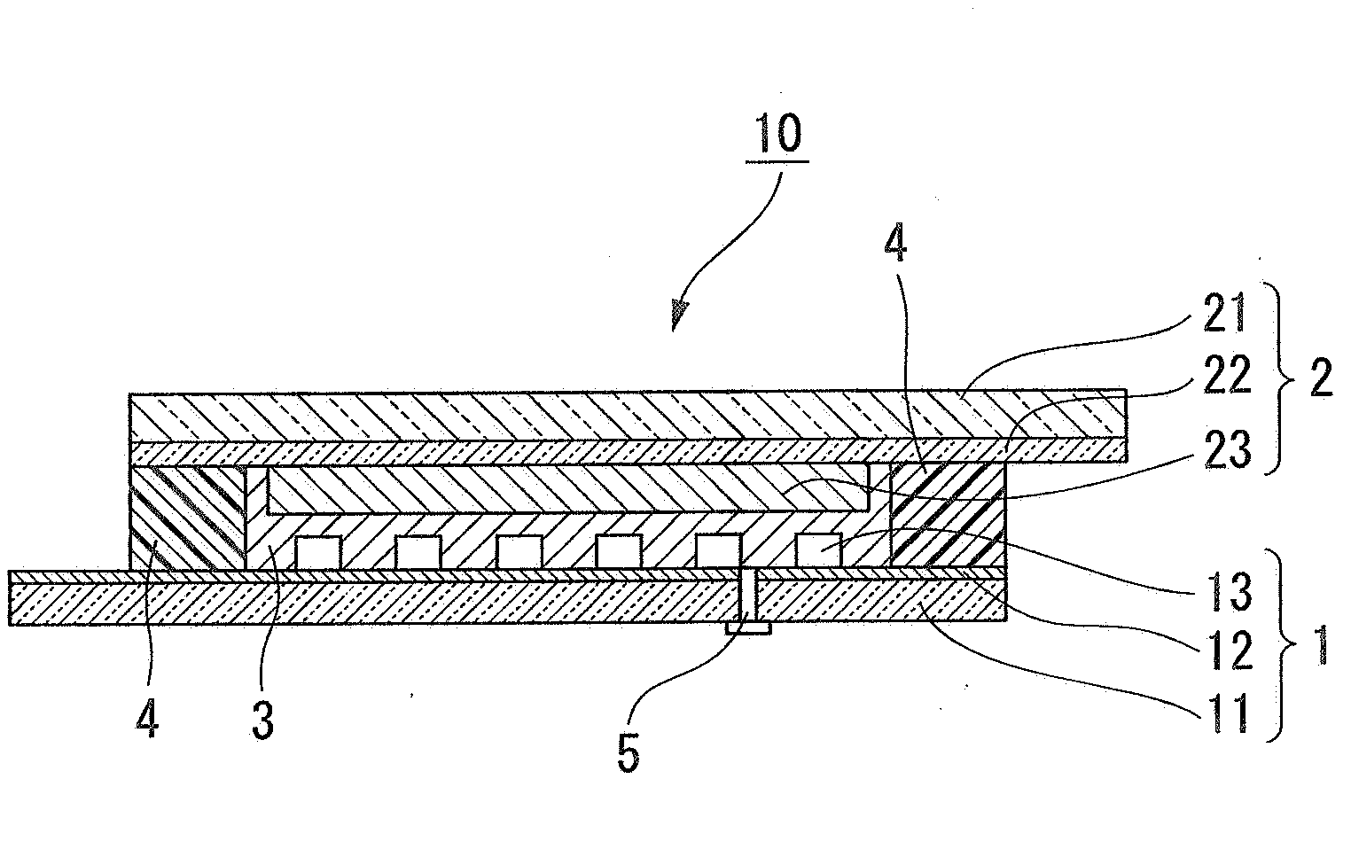
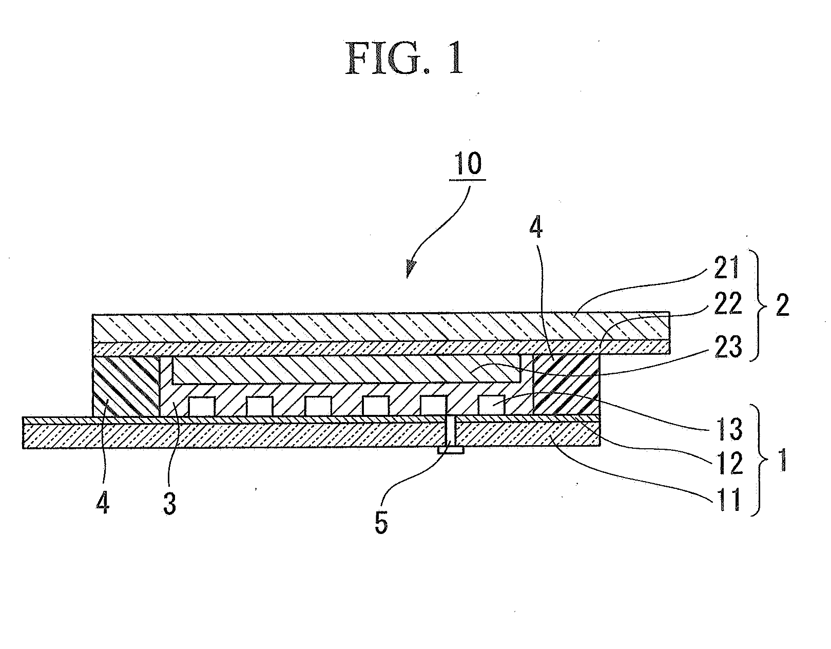
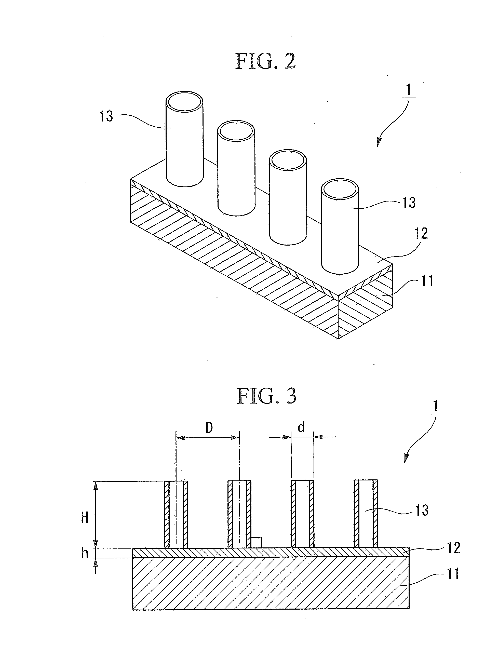
[0069]A photoelectric conversion element with a structure shown in FIG. 1 that has a counter electrode as in FIG. 2 and FIG. 3 was fabricated using the following materials.

Electrolyte

[0070]As an electrolyte of Example 1, Example 3, and Example 4, an electrolyte solution made of an ionic liquid including iodine / iodide ion redox pairs (1-ethyl-3-imidazolium-bis(trifluoromethylsulfonyl)imide) was prepared.

[0071]As an electrolyte of Example 2, Example 5, and Example 6, a nanocomposite gel electrolyte that was made by mixing 10 wt % of oxide titanium nanoparticles with it, followed by centrifugal separation.

Window Electrode

[0072]A glass substrate with an FTO film was used as a transparent electrode substrate. On a surface of the FTO film side of the transparent electrode substrate, a slurry-like dispersion solution of oxide titanium with an average particle size of 20 nm was coated. After it was dried, the substrate was subjected to a heating treatment at a temperature of 450° C. for one...


PUM


Abstract

A photoelectric conversion element including: (1) a window electrode having a transparent substrate and a semiconductor layer provided on a surface of the transparent substrate, a sensitizing dye being adsorbed on the semiconductor layer; (2) a counter electrode having a substrate and a conductive film, provided on a surface of the substrate, that is arranged so as to face the semiconductor layer of the window electrode, and wherein the counter electrode has carbon nanotubes provided on the substrate surface via the conductive film; and (3) an electrolyte layer disposed at least in a portion between the window electrode and the counter electrode.

Description

CROSS-REFERENCE TO RELATED APPLICATION[0001]This application is a National Stage entry of PCT Application No. PCT / JP2005 / 022485 filed Dec. 7, 2005, and claims priority from Japanese Patent Application No. 2004-371703, filed on Dec. 22, 2004, and Japanese Patent Application No. 2005-278096, filed on Sep. 26, 2005, the contents of which are incorporated herein by reference.TECHNICAL FIELD[0002]The present invention relates to a structure of a counter electrode for use in a photoelectric conversion element such as a Dye Sensitized Solar Cell.BACKGROUND ART[0003]Solar cells as a source of clean energy have attracted attention against the backdrop of environmental issues and resource issues. Some solar cells use monocrystalline, polycrystalline, or amorphous silicon. However, these related art silicon-based solar cells have persistent problems such as high manufacturing costs and insufficient raw materials, and thus are not yet in wide spread use.[0004]In contrast to this, a Dye Sensitiz...

Claims


Application Information

Patent Timeline
IPC IPC(8): H01L31/00
CPCB82Y10/00B82Y30/00H01G9/2022H01G9/2031H01G9/2059Y02E10/542H01L51/444H01M4/583H01M14/005H01M2004/022H01L51/0048Y02E60/10H10K85/221H10K30/821H01M14/00
Inventor USUI, HIROKITANABE, NOBUOMATSUI, HIROSHI
Owner THE FUJIKURA CABLE WORKS LTD
Why Eureka
Try Eureka