Carbon nanomaterial functionalized needle tip modified by low work function material and preparation method of carbon nanomaterial functionalized needle tip

A carbon nanomaterial, low work function technology, which is applied in the field of carbon nanomaterial functionalized needle tips modified by low work function materials and its preparation, can solve the problem that the carbon nanocone functionalized needle tip has not been reported yet, and the functionalized needle tip has not been reported yet, etc. problem, to achieve the effect of improving the electron emission performance

Pending Publication Date: 2021-08-06
THE NAT CENT FOR NANOSCI & TECH NCNST OF CHINA
View PDF4 Cites 0 Cited by
  • Summary
  • Abstract
  • Description
  • Claims
  • Application Information

AI Technical Summary

Problems solved by technology

So far, carbon nanocones functionalized with such low work function materials have not been reported.
On the other hand, there are currently many reports on metal compound-modified carbon nanotube composites [12] , but metallofullerene clathrate-modified carbon nanotube functionalized tips have not been reported

Method used


Image

  • Carbon nanomaterial functionalized needle tip modified by low work function material and preparation method of carbon nanomaterial functionalized needle tip
  • Carbon nanomaterial functionalized needle tip modified by low work function material and preparation method of carbon nanomaterial functionalized needle tip
  • Carbon nanomaterial functionalized needle tip modified by low work function material and preparation method of carbon nanomaterial functionalized needle tip

Examples


Embodiment 1

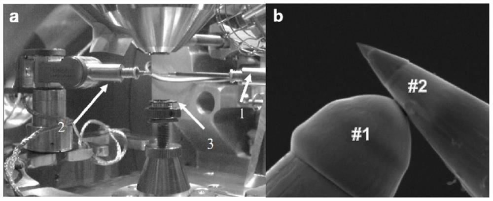
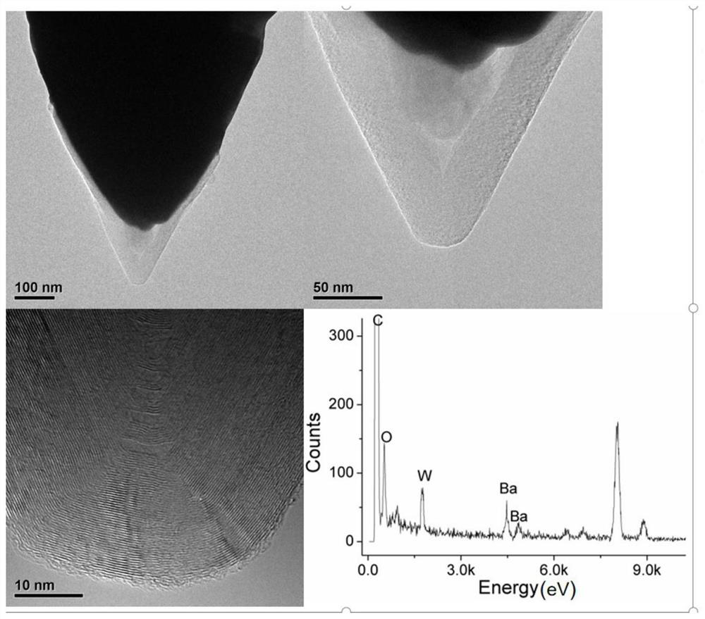
[0079] In this embodiment, the metal W needle tip is plated with a 5 nm thick Ba film (Ba target purity: 99.99%) on the surface by electron beam evaporation coating method, number #2. The carbon nanocone material is ultrasonically dispersed in o-dichlorobenzene solvent, and the obtained dispersion is deposited on the silicon wafer substrate by using a film flinger, and then the silicon wafer substrate is installed on the sample stage 3 of the scanning electron microscope, and the tungsten tip #1 and #2 are respectively installed in figure 1 On the needle tube at the front end of the No. 1 and No. 2 micro-manipulator arms, the tungsten needle tip can be moved in three-dimensional space in the scanning electron microscope sample chamber by controlling the micro-manipulator arm.

[0080] Move tungsten tip #1 so that the tip lightly touches 50 μm from the tip of tungsten probe #2 to form a path. By applying a bias voltage of 50 V, the tip of #1 tungsten probe is immediately melted...

Embodiment 2

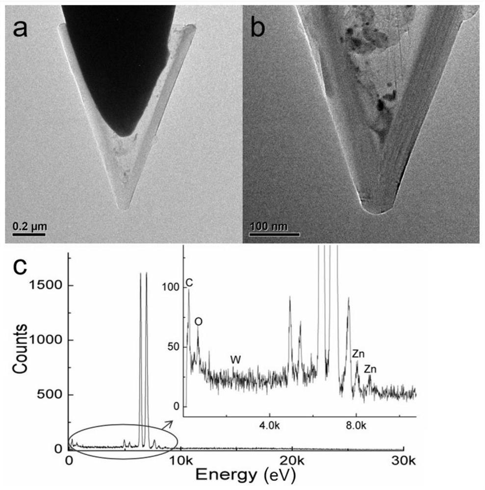
[0083] In this embodiment, the metal W needle tip is coated with a 5nm thick ZnO film (purity of the ZnO target by magnetron sputtering: 99.99%) on the surface by magnetron sputtering coating method, number #2. The carbon nanocone material is ultrasonically dispersed in o-dichlorobenzene solvent, and the obtained dispersion is deposited on the silicon wafer substrate by using a film flinger, and then the silicon wafer substrate is installed on the sample stage 3 of the scanning electron microscope, and the tungsten tip #1 and #2 are respectively installed in figure 1 On the needle tube at the front end of the No. 1 and No. 2 micro-manipulator arms, the tungsten needle tip can be moved in three-dimensional space in the scanning electron microscope sample chamber by controlling the micro-manipulator arm.

[0084] Move tungsten tip #1 so that the tip lightly touches 50 μm from the tip of tungsten probe #2 to form a path. By applying a bias voltage of 50 V, the tip of #1 tungsten ...

Embodiment 3

[0087] In this embodiment, the metal W needle tip is coated with a 5nm thick LaB6 film (LaB6 target purity: 99.99%) on the surface by electron beam evaporation coating method, number #2. The carbon nanocone material is ultrasonically dispersed in o-dichlorobenzene solvent, and the obtained dispersion is deposited on the silicon wafer substrate by using a film flinger, and then the silicon wafer substrate is installed on the sample stage 3 of the scanning electron microscope, and the tungsten tip #1 and #2 are respectively installed in figure 1 On the needle tube at the front end of the No. 1 and No. 2 micro-manipulator arms, the tungsten needle tip can be moved in three-dimensional space in the scanning electron microscope sample chamber by controlling the micro-manipulator arm.

[0088] Move tungsten tip #1 so that the tip lightly touches 50 μm from the tip of tungsten probe #2 to form a path. By applying a bias voltage of 50 V, the tip of #1 tungsten probe is immediately mel...


PUM

PropertyMeasurementUnit
electron work functionaaaaaaaaaa
purityaaaaaaaaaa

Abstract

The invention belongs to the field of metal material functionalization and relates to a carbon nanomaterial functionalized needle tip modified by a low work function material and a preparation method of the carbon nanomaterial functionalized needle tip. The carbon nanomaterial functionalized needle tip modified by the low work function material of the invention is formed by combining a carbon nanomaterial with a material of a needle tip through a covalent bond; the low work function material modifies the inside or the outer surface of the carbon nanomaterial; the needle tip is made of metal which is selected from one or more of tungsten, iron, cobalt, nickel and titanium; the carbon nanomaterial is a carbon nanocone or a carbon nanotube, and the orientation of the tip of the carbon nanomaterial is consistent with that of the metal needle tip; the low work function material is selected from one or more of a metal, a metal carbide, a metal oxide, a boride, a nitride and a metal fullerene inclusion compound. The carbon nanomaterial functionalized needle tip has a lower electron emission barrier, so that the electric field intensity required by electron emission can be effectively reduced, and the emission current and the emission efficiency are improved.

Description

technical field [0001] The invention relates to the field of metal material functionalization, in particular to a carbon nanometer material functionalized needle tip modified by a low work function material and a preparation method thereof. Background technique [0002] Based on the novel physical and chemical properties of nanomaterials, nanomaterial functionalized tips have a wide range of applications in electron emission sources, scanning probe microscopes, vacuum electronic devices, biomedicine and other fields. Conventional nanomaterial-functionalized needle tips use physical adsorption to adhere nanomaterials (including nanowires, nanotubes, etc.) to the front end of the needle tip substrate. [1] , and deposit carbon or platinum material between the nanomaterial and the tip substrate to fix it [2-4] . The carbon nanotube functionalized tip is prepared by the above method and used in field emission research. The nanomaterial-metal interface of this functionalized ne...

Claims


Application Information

Patent Timeline
Patent Type & Authority Applications(China)
IPC IPC(8): H01J37/04H01J37/28H01J9/04
CPCH01J37/04H01J37/28H01J9/042H01J1/3044H01J2201/30415H01J2201/30426H01J2201/30469H01J2237/06341H01J9/025B81B1/008G01Q70/12G01R1/06738G01R1/0675
Inventor 徐建勋赵宇亮葛逸飞
Owner THE NAT CENT FOR NANOSCI & TECH NCNST OF CHINA
Why Eureka
Try Eureka