Method and plant for re-gasification of LNG

a technology of regasification and plant, which is applied in the direction of steam engine plants, gas/liquid distribution and storage, lighting and heating apparatus, etc., can solve the problems of large seawater intake system, large amount of seawater, so as to improve the total energy efficiency and profitability of the plant, avoid or improve the energy efficiency of the plan

Inactive Publication Date: 2009-11-12
AKER KVRNER ENG & TECH
View PDF13 Cites 12 Cited by
  • Summary
  • Abstract
  • Description
  • Claims
  • Application Information

AI Technical Summary

Benefits of technology

[0021]According to a third aspect, the present invention provides for the use of LNG for cooling air in an air separation unit to produce substantially pure oxygen. The use of the cold LNG for cooling of the air for the air separation unit avoids or reduces the need for additional cooling of the incoming air, and adds heat to the re-gasification, to improve the energy efficiency of the plant.
[0022]According to one embodiment, other air gases such as argon, nitrogen, helium are separated in the air separation unit for other uses or sales. The separation of other air gases may improve the total energy efficiency and profitability of the plant.

Problems solved by technology

A huge amount of seawater is needed with the normally limited temperature drop allowed in the seawater used as the heat source.
However, in the later studies environmentalists have expressed objections to both intake / chlorination and outlet / temperature changes, since both have undesirable effects on the marine life.
Additionally the seawater intake system is large, and thus costly since the water inlet velocity in the strainers is kept very low to limit the unfavorable effects on marine life.
The discharges to the atmosphere from power generation and from the SCVs has unfavorable effects on the air quality.
Many locations that would otherwise be attractive for a LNG receiving terminal may thus be found not acceptable for air quality reasons.

Method used


Image

  • Method and plant for re-gasification of LNG
  • Method and plant for re-gasification of LNG

Examples


example

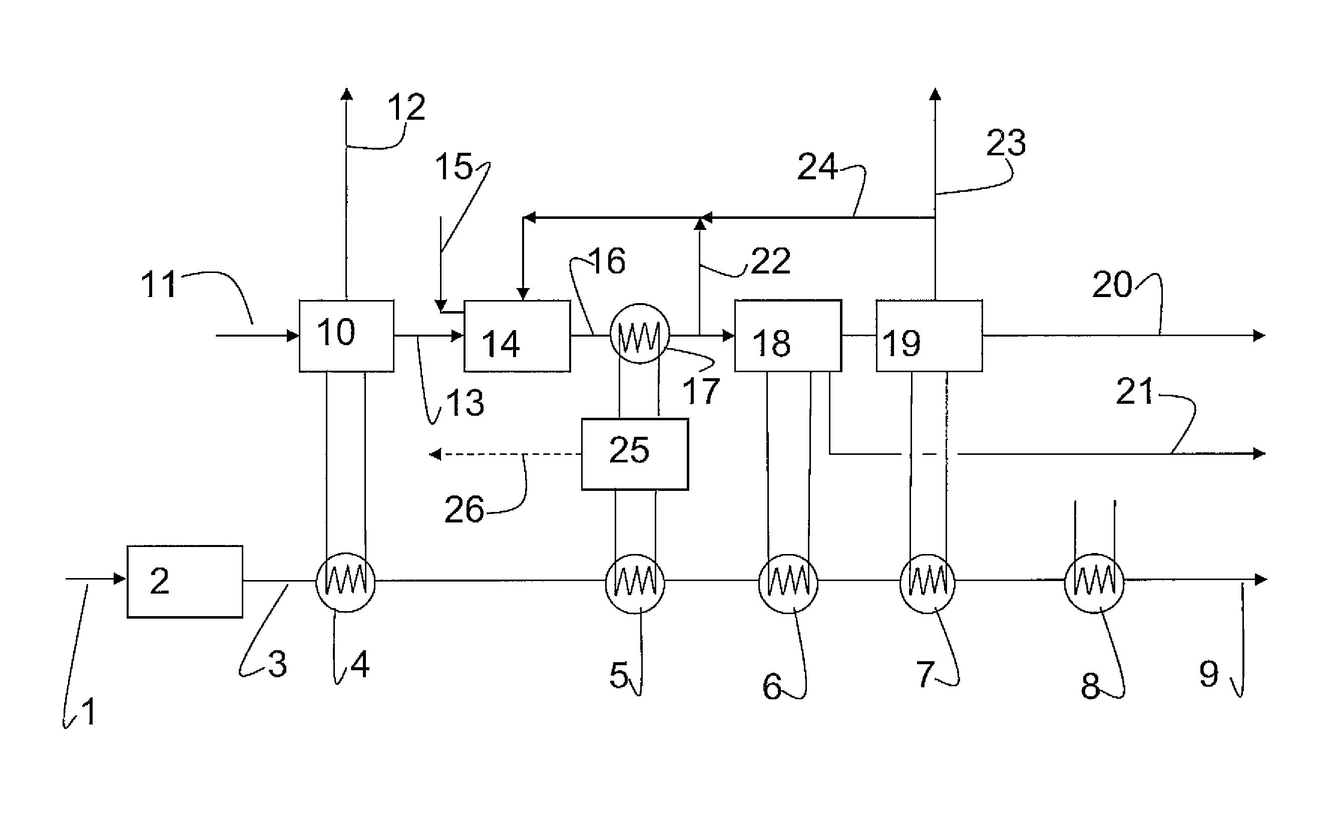
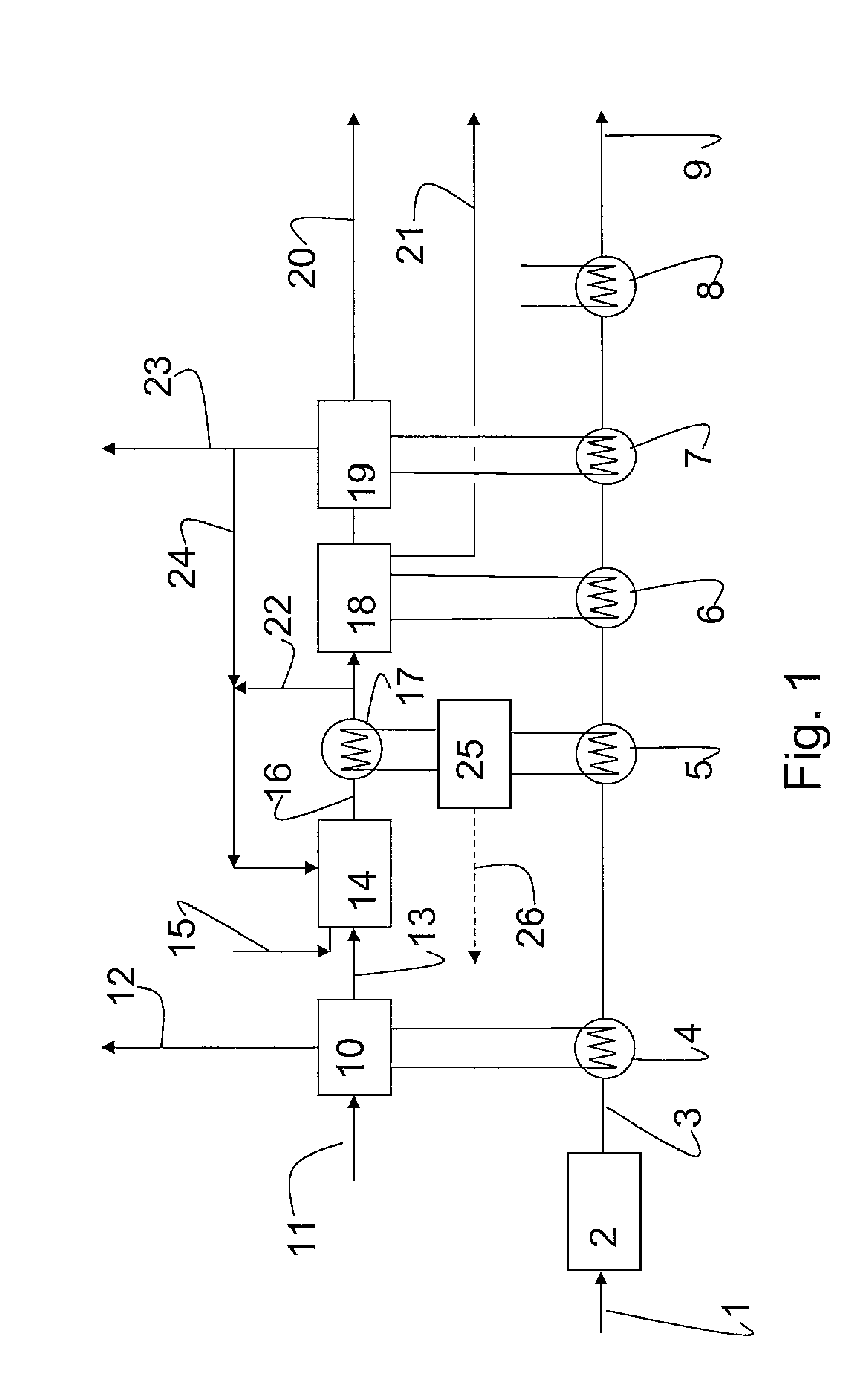
[0034]An exemplary LNG re-gasification plant for the re-gasification of 1717 t / h (2 BSCFD) of LNG, has been simulated.

[0035]The non discharge regasification system as explained above has been estimated for an LNG facility with 1717 t / h (2BSCF / D) sales gas (9). The burner (14) will require additional 23.4 t / h of natural gas (15) to be burned with 93.1 t / h pure oxygen (13). Almost 700 t / h CO2 is recirculated to the burner (22 and 24). A vent line from the CO2 liquefaction unit discharge 2.5 t / h, mostly CO2 with some N2, Ar and O2, to the atmosphere (23).

[0036]The steam power system (25) produce the 55MW electrical power (26) required by the Regasification plant. In addition to the sales gas, the plant further produce:[0037]About 50 t / h liquefied CO2 at −38° C. from the liquefaction unit (19).[0038]About 50 t / h fresh water from the CO2 dryer train (18).[0039]The large amount of N2 vent (12) to the atmosphere from the ASU (10) is not regarded as a pollutant

[0040]The “Non-Discharge Regas...


PUM


Abstract

A method for re-gasification of LNG in which method natural gas is combusted in a burner to provide heat for evaporation of the LNG and where the heat is transferred from the burner to the LNG in a closed heat exchange system, wherein substantially pure oxygen is used in the combustion of natural gas, and that C02 is separated from the exhaust gas for export or deposition, is described. A plant for re-gasification of LNG, the plant comprising a gas fired burner (14) for generation of heat for the re-gasification, a closed heat exchange system (5, 17,25) for transfer of heat from the burner to LNG to be vaporized, the plant additionally comprising a air separation unit (10) for generation of substantially pure oxygen to be fed to the burner (14), is also described.

Description

THE FIELD OF INVENTION[0001]The present invention relates to an environmental friendly re-gasification process for LNG. More specifically the invention relates to a method and plant for re-gasification of LNG, that allows for re-gasification of LNG with no, or substantially reduced, environmental impact, such as cooling of seawater and emission of CO2 to the atmosphere.TECHNICAL BACKGROUND[0002]LNG (Liquefied Natural Gas) is a method for transporting methane gas over long distances. The gas is liquefied prior to transport from the gas production location and is transported as a cooled liquid in LNG carriers. The tankers delivers the LNG to a LNG re-gasification terminal comprising LNG tanker unloading facilities, LNG storage tanks, re-gasification units and gas export pipeline(s).[0003]The LNG has to be re-gasified before it can be transmitted through a pipeline distribution network. The re-gasification takes place in the re-gasification unit. Traditionally, two different vaporizing...

Claims


Application Information

Patent Timeline
Patent Type & Authority Applications(United States)
IPC IPC(8): F17C9/04
CPCF01K13/00F17C2270/0105F02C3/22F17C9/04F22B1/1838F25J1/0027F25J1/0221F25J3/04266F25J3/04533F25J2210/62F25J2220/82F25J2260/80F17C2221/033F17C2223/0161F17C2223/033F17C2225/0123F17C2227/0135F17C2227/0157F17C2227/0311F17C2227/0323F17C2227/0332F17C2227/0353F17C2227/0365F17C2227/039F17C2260/044F17C2265/05F17C2265/07F01K15/00F25J3/00
Inventor EIE, ROLFVIGANDER, KJELL
Owner AKER KVRNER ENG & TECH
Why Eureka
Try Eureka