
Inkjet recording method and inkjet recording apparatus

a recording method and inkjet technology, applied in the direction of inks, duplicating/marking methods, coatings, etc., can solve the problems of undried ink staining of reversal rollers, time-consuming process, and difficult ink penetration into recording medium, etc., to achieve high drying speed and high quality

Active Publication Date: 2009-11-26
RICOH KK
View PDF2 Cites 59 Cited by
  • Summary
  • Abstract
  • Description
  • Claims
  • Application Information

AI Technical Summary

Benefits of technology

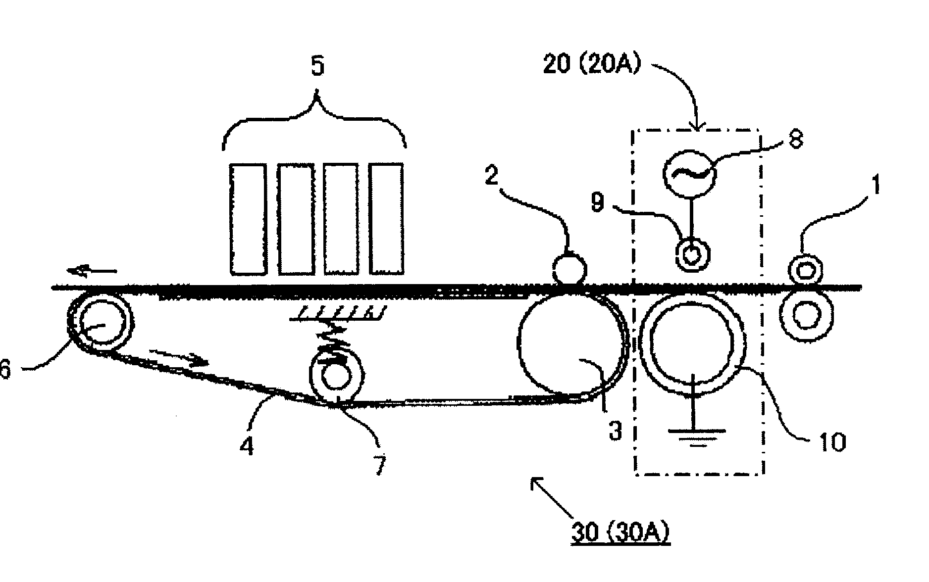
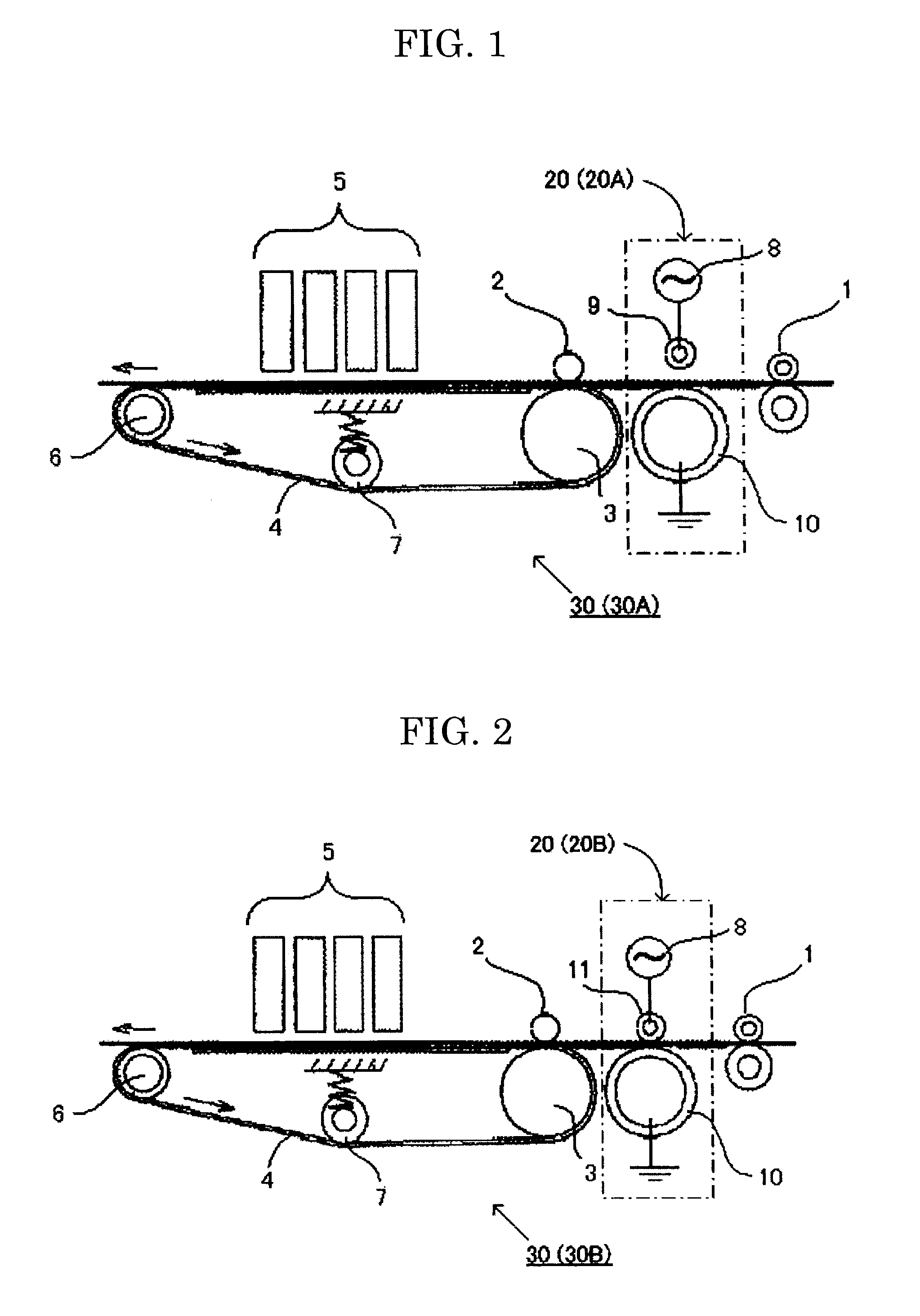
[0016]The object of the present invention is to provide an inkjet recording method and an inkjet recording apparatus, which solve the above conventional problems, and can produce a high-density, high quality image with high drying speed.
[0017]To solve the above-mentioned problems, the present inventors have conducted extensive studies. As a result, they have found that a recording medium whose surface is hydrophilized by exposing the surface to non-thermal atmospheric pressure plasma does not undergo any deformation such as waving due to the shrink of paper fiber, and has a high water-absorption property; and that if an ink composition containing at least one of a pigment / water-dispersible resin particles mixture in which a pigment is dispersed along with a water-dispersible resin particles and a colored water-dispersible resin particles is used to record (print) images or the like on the hydrophilized recording medium, a high density, high quality images can be obtained with at a high drying speed, leading to the accomplishment of the present invention.
[0028]According to the present invention, the conventional problems as mentioned above can be solved, and an inkjet recording method and an inkjet recording apparatus are provided, capable of obtaining images of a high drying speed, high density and high quality.

Problems solved by technology

Accordingly, it is hard for an ink to permeate into the recording medium, so that drying thereof is a time-consuming process.
For example, in a high-speed automatic duplex printing, a one-surface-printed paper is promptly reversed and subjected to the back face printing in an inkjet recording apparatus, which tend to cause a problem that reversal rollers are stained with undried ink.
Meanwhile, when the ink adhesion amount is increased for the purpose of increasing an image density, more time is needed for drying, and image quality tends to degrade due to the feathering of the image.
However, if ink heating is performed during printing process or the like, an inkjet head tends to be deformed by heat, resulting in the degradation of injection stability such as nozzle clogging.
In some cases, the paper is even damaged by drying.
However, such a heating tends to overdry the fibers of paper and shrinks them, resulting in the waving of the paper.
Further, the paper waving becomes more noticeable with partial swelling of the paper fibers due to the absorption of ink, causing excess elevation of humidity in the apparatus.
Furthermore, when the paper waves, an ink ejecting distance directly under the inkjet head varies with the move of the paper, resulting in the occurrence of unevenness in the color image formed by overlapping a plurality of colors.

Method used


Image

  • Inkjet recording method and inkjet recording apparatus
  • Inkjet recording method and inkjet recording apparatus

Examples


production example 1

—Preparation of Surface Treated Black Pigment Dispersion—

[0136]To 3,000 mL of 2.5 N sodium sulfate solution, 90 g of a carbon black having a CTAB specific surface area of 150 m2 / g and a DBP oil absorbing amount of 100 mL / 100 g was added, and the mixture was stirred for 10 hours at 60° C. and at 300 rpm for oxidation.

[0137]Thereafter, the reaction mixture was filtered and the obtained carbon black was neutralized with sodium hydroxide solution, followed by ultrafiltration. The resultant carbon black was washed with water and dried, and dispersed into pure water such that a solid content is 20% by mass, whereby the black pigment dispersion of Production Example 1 was yielded.

production example 2

—Preparation of Polymer Solution A—

[0138]In a 1 L flask equipped with a mechanical stirrer, thermometer, nitrogen gas-introducing tube, reflux tube, and dropping funnel, nitrogen gas was passed thoroughly, and then styrene (11.2 g), acrylic acid (2.8 g), laurylmethacrylate (12.0 g), polyethylene glycol methacrylate (4.0 g), styrene macromer (AS-6, produced by Toagosei Co., Ltd.) (4.0 g), and mercaptoethanol (0.4 g) were mixed in the flask, and the mixture was heated to 65° C.

[0139]Then, into the flask, a mixed solution of styrene (100.8 g), acrylic acid (25.2 g), laurylmethacrylate (108.0 g), polyethylene glycol methacrylate (36.0 g), hydroxyethylmethacrylate (60.0 g), styrene macromer (AS-6, produced by Toagosei Co., Ltd.) (36.0 g), mercaptoethanol (3.6 g), azo bismethyl valeronitrile (2.4 g), and methyl ethyl ketone (18 g) was dropped for 2.5 hours.

[0140]After completion of the dropping, a mixed solution of azo bismethyl valeronitrile (0.8 g) and methyl ethyl ketone (18 g) was dro...

production example 3

—Preparation of Copper Phthalocyanine Pigment-Containing Polymer Fine Particle Dispersion—

[0142]A water dispersion of a cyan polymer fine particle was prepared in the same manner as in the Production Example 2 except that C. I. Pigment Red 122 was changed to copper phthalocyanine, and pigment content and solid content were changed to 12% by mass and 20% by mass, respectively.


PUM

PropertyMeasurementUnit
Percent by massaaaaaaaaaa

Abstract

An inkjet recording method including: (i) exposing a surface of a recording medium to non-thermal atmospheric pressure plasma so as to hydrophilize the surface of the recording medium, and (ii) applying a stimulus to an ink composition so as to eject the ink composition to form an image on the recording medium, wherein the ink composition contains at least one of a pigment / water-dispersible resin particle mixture in which a pigment is dispersed along with water-dispersible resin particles and colored water-dispersible resin particles each of which is a water-dispersible resin particle which is colored.

Description

BACKGROUND OF THE INVENTION[0001]1. Field of the Invention[0002]The present invention relates to an inkjet recording method and inkjet recording apparatus.[0003]2. Description of the Related Art[0004]An inkjet recording method is a method for recording images or the like, in which small liquid drops of ink are jetted and attached to a recording medium such as paper. In the inkjet recording method, an ink composition is generally used which contains various colorants such as dyes and pigments dissolved in water or a mixture of water and organic solvent, and a large quantity of wetting agents consisting of organic solvents having a high boiling point.[0005]In the inkjet recording method, as a recording medium, a recording medium having poor water-absorbing capacity such as commonly used plain paper is sometimes used, in place of an inkjet-dedicated paper excellent in water absorbability. These recording media do not necessarily have an absorbing layer. Accordingly, it is hard for an i...

Claims


Application Information

Patent Timeline
IPC IPC(8): B41J2/01B41M5/00B41M5/50B41M5/52
CPCC09D11/322B41J11/0015B41M5/0011B41M5/0047B41M5/0064
Inventor SAITOH, HARUKIOGATA, HIJIRI
Owner RICOH KK
Learn More