Plasma reactor with internal transformer

a technology of plasma reactor and transformer, which is applied in the direction of machines/engines, process and machine control, instruments, etc., can solve the problems of difficult stably keeping plasma, negative output, damage to the inside surface of the plasma reactor, etc., and achieves the effect of preventing many problems, simple manufacturing, and high energy transfer efficiency

Inactive Publication Date: 2009-11-26
NEW POWER PLASMA CO LTD
View PDF5 Cites 41 Cited by
  • Summary
  • Abstract
  • Description
  • Claims
  • Application Information

AI Technical Summary

Benefits of technology

[0049]In accordance with the plasma reactor with the internal transformer of the present invention, since the transformer is installed in the plasma chamber, energy is transferred with almost no loss from the transformer to the plasma discharging space and thus the energy transfer efficiency is very high. Therefore, the plasma reactor is very suitable for generating large amount of active gases. Further, even though the plasma chamber is composed of a conductive material, since no special insulating region needs to be formed, it is very easy to constitute the plasma chamber. Further, since the plasma chamber itself is sufficiently capable of forming an outer case, the plasma reactor is very simply manufactured. When two or more transformers are used, relatively large amount of active gas is generated. Further, the plasma reactor with the internal transformer(s) can be effectively used when supplying the active gas to the process chamber through a number of gas outlets. Further, since the plasma reactor uses a number of low-capacity transformers, it is capable of preventing many problems that may be caused when one high-capacity transformer is used.

Problems solved by technology

However, in the type of inductively coupled plasma, a high-voltage driving coil is used because the energy binding with plasma is low compared with the energy as supplied.
Consequently, since the ion energy is high, the 10 inside surface of a plasma reactor may be damaged by ion bombardment.
The damage to the inside surface of a plasma reactor by the ion bombardment not only shortens the life of the plasma reactor but also influences as a pollution source of plasma processing, resulting in a negative output.
Therefore, in the inductively coupled plasma, it is difficult to stably keep plasma.
However, since the volume of a process chamber increases as a substrate to be processed becomes larger, a plasma source needs to remotely supply a sufficient amount of high-density active gas.
Then, when the size of the reactor increases, it is not easy to install the reactor.
The plasma chamber having the aforementioned separate structure may have the problem of lowering the security and coherence in installing a large-volume plasma reactor.
Moreover, when a radio frequency generator and a plasma reactor are constituted in a single unit like a conventional technique, it is more likely to have the aforementioned problem.

Method used


Image

  • Plasma reactor with internal transformer
  • Plasma reactor with internal transformer
  • Plasma reactor with internal transformer

Examples


exemplary embodiment 1

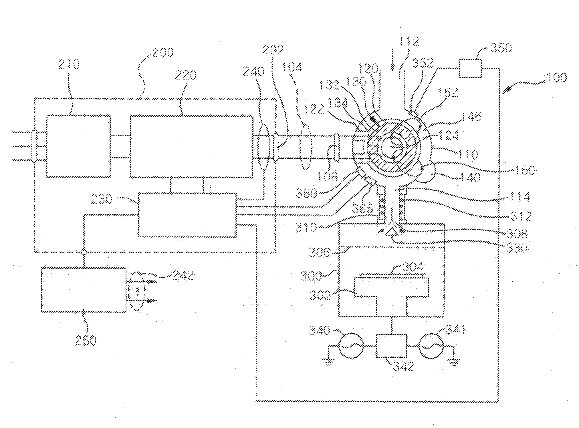
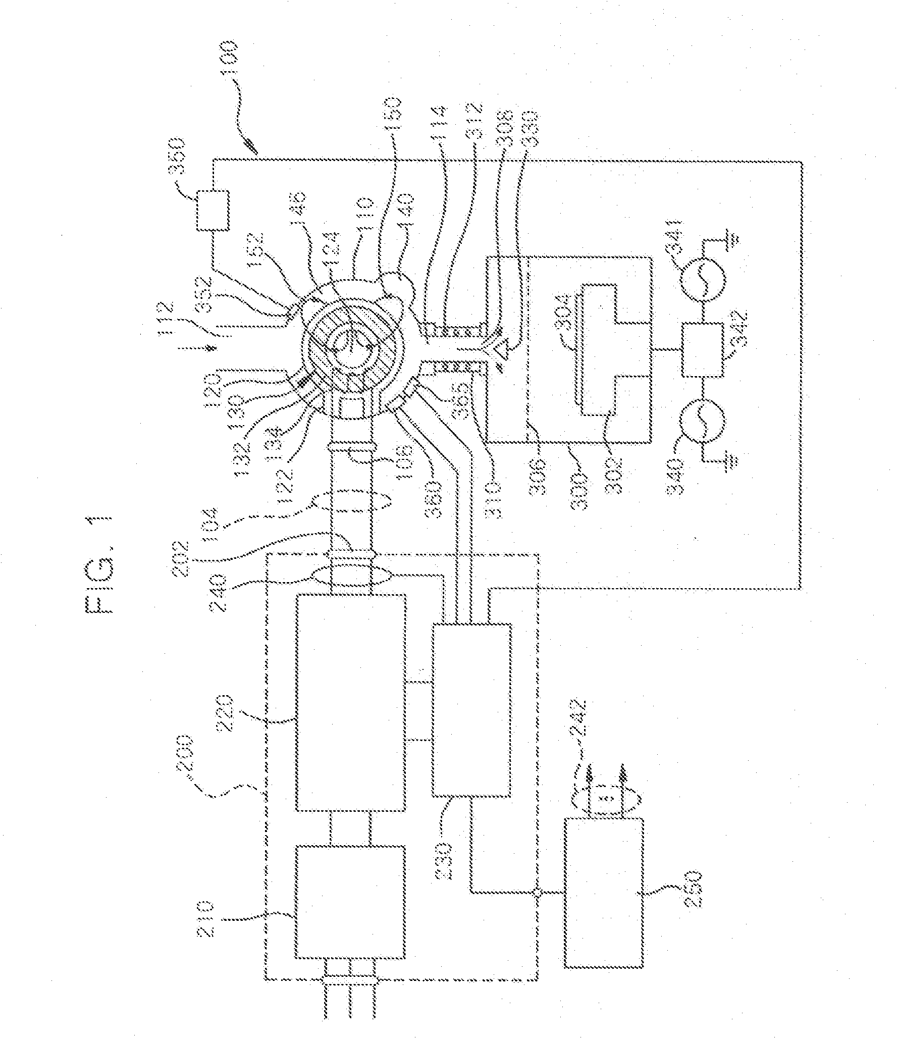
[0079]FIG. 1 illustrates a plasma processing apparatus including a plasma reactor 100 according to a preferred embodiment of the present invention.

[0080]Referring to FIG. 1, the plasma reactor 100 comprises a plasma chamber 110 in which a transformer 130 is installed. The plasma chamber 110 provides a plasma discharging space with a gas inlet 112 and a gas outlet 114. A core cylinder jacket 120 to provide a core storage space is included in the plasma chamber 110. The core cylinder jacket 120 is spaced apart from an inside wall of the plasma chamber 110 and is connected to the plasma chamber 110 through a connection bridge 122. The core storage space of the core cylinder jacket 120 is operatively connected to the outside of the plasma chamber 110 through the connection bridge 122. The transformer 130 is installed in the core storage space of the core cylinder jacket 120. The transformer 130 includes a magnetic core 132 with a primary winding 134. The magnetic core 132 is installed i...


PUM


Abstract

There is provided a plasma reactor with an internal transformer. The plasma reactor comprises: a plasma chamber with a gas inlet and a gas outlet, for providing a plasma discharging space; one or more core cylinder jackets for providing a core storage space in the plasma discharging space and forming a plasma centralized channel and a plasma decentralized channel by including one or more through-apertures; and one or more transformers each including a magnetic core with primary winding surrounding the through-aperture and installed in the core storage space, wherein the plasma discharging space comprises one or more first spatial regions to form the plasma centralized channel and one or more second spatial regions to form the plasma decentralized channel. In the plasma reactor, since the transformer is installed in the plasma chamber, energy is transferred with almost no loss from the transformer to the plasma discharging space and therefore the energy transfer efficiency is very high. Then, since most of gases flow through the first spatial region and the through-aperture inside the plasma chamber, most of active gases are generated in the plasma centralized channel. Consequently, the plasma reactor is very suitable for generating large amount of active gases. Further, even though the plasma chamber is composed of a conductive material, since no special insulating region needs to be formed, it is very easy to constitute the plasma chamber. Further, since the plasma chamber itself is sufficiently capable of forming an outer case, the plasma reactor is very simply manufactured.

Description

CROSS-REFERENCE TO RELATED APPLICATION[0001]This application claims the benefit of Korean Patent Application No. 10-2008-46796, filed May 20, 2008, the disclosure of which is hereby incorporated herein by reference in its entirety.BACKGROUND OF THE INVENTION[0002]1. Technical Field[0003]The present invention relates to a plasma reactor for generating an active gas including ions, free radicals, atoms and molecules by plasma discharging and performing plasma processing of a solid, powder, gas or the like by using the active gas and, more particularly, to a multi-path inductively coupled plasma.[0004]2. Discussion of Related Art[0005]Plasma discharge is used for gas excitation to generate an active gas including ions, free radicals, atoms and molecules. An active gas is widely used in various fields. An active gas is generally used in semiconductor fabrication processes, for example, such as etching, deposition, cleaning, ashing and the like.[0006]A wafer for fabricating a semiconduct...

Claims


Application Information

Patent Timeline
Patent Type & Authority Applications(United States)
IPC IPC(8): B01J19/08G05D99/00
CPCH05H1/46B82Y40/00H05H1/24H05H1/36
Inventor CHOI, DAE-KYU
Owner NEW POWER PLASMA CO LTD
Why Eureka
Try Eureka