Copper foil with carrier sheet, method for manufacturing copper foil with carrier sheet, surface-treated copper foil with carrier sheet and copper-clad laminate using the surface-treated copper foil with carrier sheet

a carrier sheet and copper foil technology, applied in the field of copper foil with carrier sheet, can solve the problems of difficult control of difficulty in quality assurance of the release strength between the carrier layer and the copper foil layer, and difficulty in ensuring the release strength, so as to achieve the effect of reducing the amount of chromium deposition, and improving the stability of the thermal resistan

Active Publication Date: 2009-11-26
MITSUI MINING & SMELTING CO LTD
View PDF3 Cites 31 Cited by
  • Summary
  • Abstract
  • Description
  • Claims
  • Application Information

AI Technical Summary

Benefits of technology

[0040]A copper-clad laminate according to the present invention: A copper-clad laminate of high quality can be provided by using the surface-treated copper foil with carrier sheet according to the present invention.
[0041]The copper foil with carrier sheet according to the present invention which has a stacked structure of carrier sheet layer/bonding interface layer/copper foil layer is characterized in that a bonding interface layer is formed by a thin film forming technologies, typically sputtering vapor deposition. As the bonding interface layer is composed of a metal layer and a carbon layer, the bonding interface layer (releasing layer) shows superior stability in thermal resistance than the conventional peelable type copper foils with carrier sheet. As a result, releasing of the carrier sheet is dramatically made ease even after hot pressing at a temperature exceeding 300° C.
[0042]Also, th

Problems solved by technology

Moreover, the release strength tends to lack stability to make quality assurance of the release strength between the carrier layer and the copper foil layer difficult.
However, as is well known to the persons skilled in the art, it is difficult to control the amount of chromium depositi

Method used


Image

  • Copper foil with carrier sheet, method for manufacturing copper foil with carrier sheet, surface-treated copper foil with carrier sheet and copper-clad laminate using the surface-treated copper foil with carrier sheet
  • Copper foil with carrier sheet, method for manufacturing copper foil with carrier sheet, surface-treated copper foil with carrier sheet and copper-clad laminate using the surface-treated copper foil with carrier sheet
  • Copper foil with carrier sheet, method for manufacturing copper foil with carrier sheet, surface-treated copper foil with carrier sheet and copper-clad laminate using the surface-treated copper foil with carrier sheet

Examples


example 1

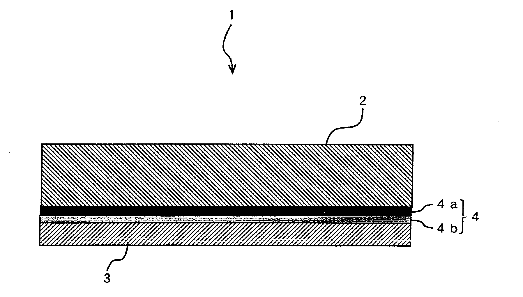
[0095]In the example 1, the first copper foil with carrier sheet 1 shown in FIG. 1 was manufactured. For the carrier sheet 2A, an electrodeposited copper foil of 35 μm thick classified to grade 3 was used, and the 3 μm thick copper foil layer 3 was formed on the shiny side where average roughness (Ra) is 0.21 μm. The production conditions will be described in step by step of processing. In the electrolysis steps described below, a dimensionally stable anode (DSA) was commonly used for the anode unless the material is otherwise stated specifically.

[0096]First, acid pickling was performed to the carrier sheet 2. In the acid pickling, the carrier sheet 2 was dipped for 30 seconds in a diluted sulfuric acid solution of 150 g / l in sulfuric acid concentration and 30° C. in solution temperature to remove the oxide film on the surface, followed by rinsing with water and then drying.

[0097]Process A: The sputtering apparatus used for the formation of the bonding interface layer on the carrier...

example 2

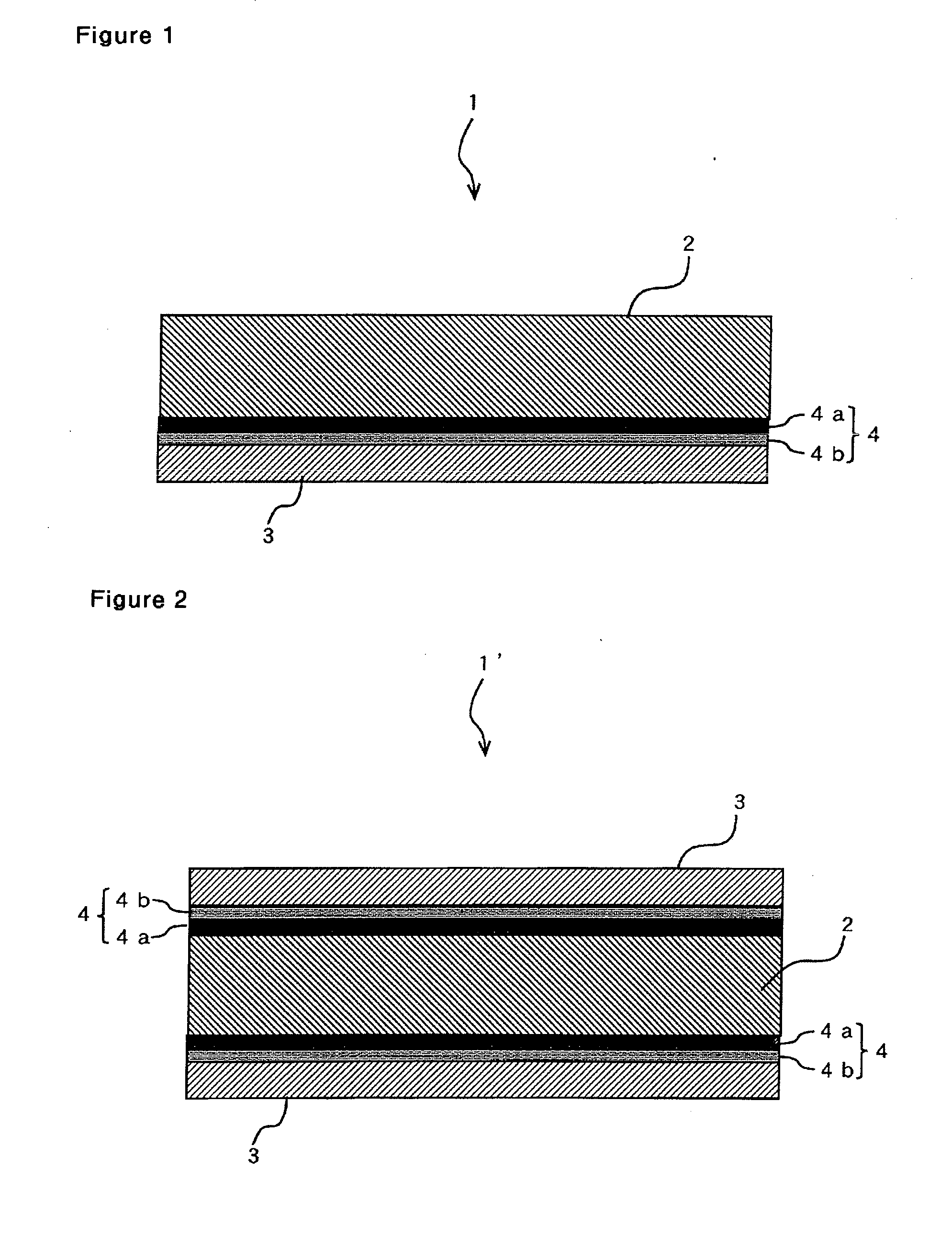
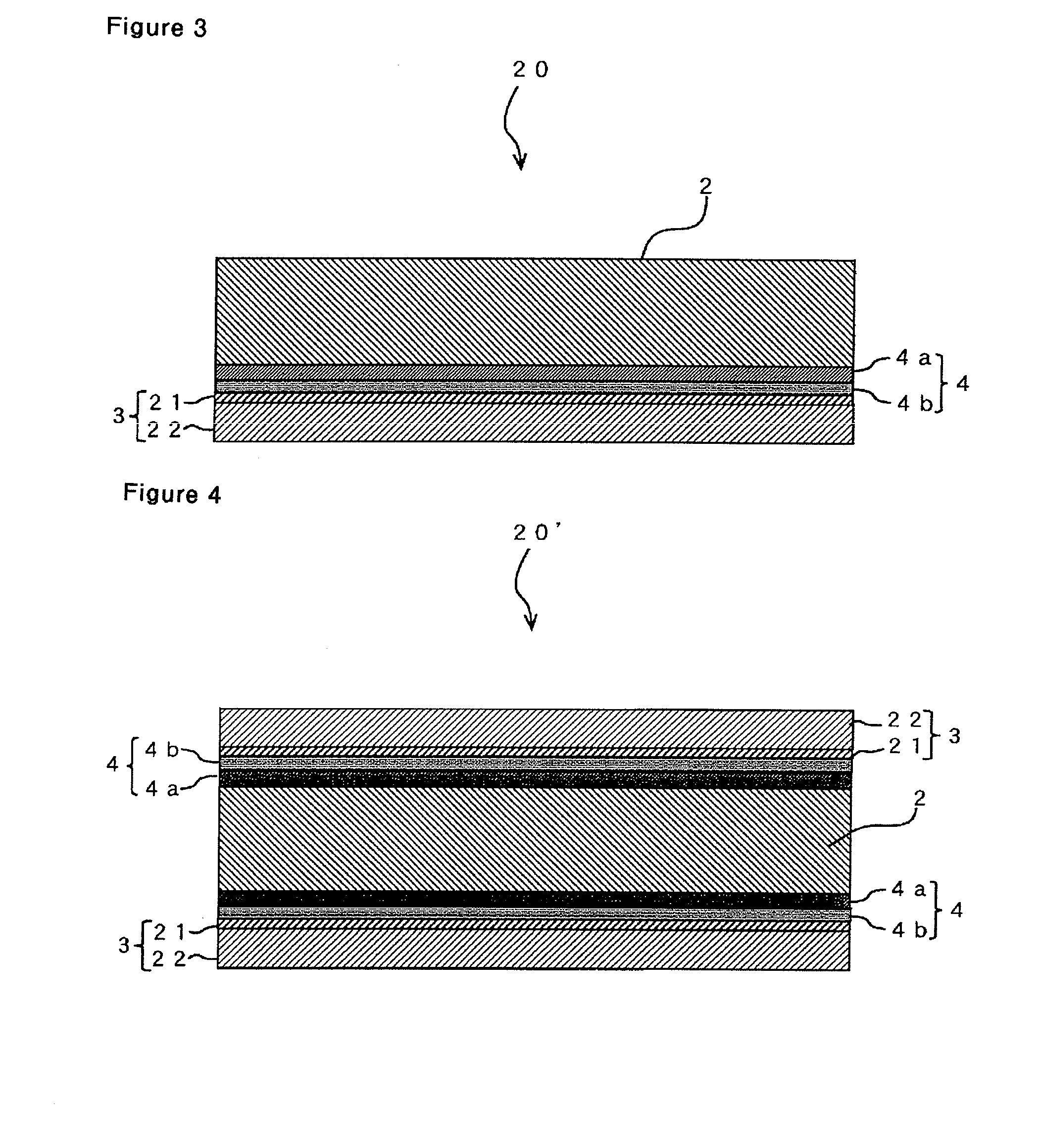
[0107]In the example 2, the result in manufacturing of the second copper foil with carrier sheet 20 shown in FIG. 2 will be described. In the example 2, the same electrodeposited copper foil as in Example 1 was used for the carrier sheet 2, and the copper foil layer 3 of 5 μm thick was formed on the shiny side where average roughness (Ra) is 0.21 μm. The manufacturing conditions will be described below in step by step of processing. In the example 2, acid pickling was performed to the carrier sheet 2 under the same conditions as in Example 1 first.

[0108]Process a: To prepare samples 1 to 4 listed in Table 1, titanium layers as metal layer having various thicknesses were formed on the carrier sheets, i.e. the shiny side of the electrodeposited copper foils, by the same method as process A of Example 1.

[0109]Then, to prepare samples 1 to 4 listed in Table 1, carbon layers of various thicknesses were formed on the titanium layers of the samples by the same method as process A of Exampl...

example 3

[0114]In the example 3, the second copper foil with carrier sheet 20 shown in FIG. 2 as manufactured in a similar process to that in Example 2. Since the process is basically the same as that in Example 2, only the different parts will be described.

[0115]First, acid pickling was performed to the carrier sheet 2. In the acid pickling, the carrier sheet 2 was dipped for 30 seconds in a diluted sulfuric acid solution of 150 g / l in sulfuric acid concentration and 30° C. in solution temperature to remove the oxide film on the surface, followed by rinsing with water and then drying.

[0116]Process a: For the formation of the bonding interface layer on the carrier sheet dried, a wind-up type sputtering apparatus SPW-155 manufactured by Nihon Shinkugijutsu Co. was used for the sputtering apparatus, and the target used was a nickel target of 300 mm×1700 mm in size. As for sputtering conditions, an achieved vacuum level Pu was less than 1×10⁻⁴ Pa, a sputtering pressure PAr was 0.1 Pa and a sput...


PUM

PropertyMeasurementUnit
Temperatureaaaaaaaaaa
Thicknessaaaaaaaaaa

Abstract

An object of the present invention is to provide a copper foil with carrier sheet which permits releasing of the carrier sheet from the copper foil layer even when hot pressing at a temperature exceeding 300° C. is applied in the production of a printed wiring board. In order to achieve the object, a copper foil with physically releasable carrier sheet having a copper foil layer on the surface of the carrier sheet through a bonding interface layer, characterized in that the bonding interface layer is composed of a metal layer and a carbon layer. It is preferable for the bonding interface layer to be composed of a metal layer of 1 nm to 50 nm thick and a carbon layer of 1 nm to 20 nm thick.

Description

TECHNICAL FIELD[0001]The present invention relates to a copper foil with carrier sheet, a method for manufacturing the copper foil with carrier sheet, a surface-treated copper foil with carrier sheet manufactured by surface-treating the copper foil with carrier sheet, and a copper-clad laminate using the surface-treated copper foil with carrier sheet. All these are suitable materials for manufacturing printed wiring boards.BACKGROUND ART[0002]Electrodeposited copper foils such as those disclosed in many literatures including Patent Document 1 and rolled copper foils such as the one disclosed in Patent Document 2 have been conventionally used for the manufacturing of copper-clad laminates. Then, the printed wiring boards have been manufactured by etching the copper layer constituting the copper-clad laminates.[0003]The manufacturing methods of copper-clad laminates are different with their type, rigid type copper-clad laminates or flexible type copper-clad laminates. In manufacturing...

Claims


Application Information

Patent Timeline
IPC IPC(8): B32B15/20B32B15/04B05D1/36C25D5/00C23C14/34C25D5/10C25D5/34
CPCC23C30/00C25D1/04C25D1/20C25D5/10C25D5/34H05K3/025H05K2201/0323Y10T428/12806Y10T428/24967Y10T428/265Y10T428/12438Y10T428/30Y10T428/12625Y10T428/12903Y10T428/24975B32B15/08C23C14/06H05K1/09
Inventor NAGATANI, SEIJIWATANABE, HIROSHIIZUMIDA, KAZUFUMI
Owner MITSUI MINING & SMELTING CO LTD
Why Eureka
Try Eureka