
Microchip electrophoresis method and device

a microchip and electrophoresis technology, applied in the direction of fluid pressure measurement, liquid/fluent solid measurement, peptide measurement, etc., can solve the problems of temperature control in microchips, high reproducibility and detection efficiency cannot be obtained, and prior technologies do not relate to techniques for separating double-stranded nucleic acids. achieve high reproducibility and detection efficiency

Inactive Publication Date: 2009-12-03
EBARA CORP
View PDF3 Cites 10 Cited by
  • Summary
  • Abstract
  • Description
  • Claims
  • Application Information

AI Technical Summary

Benefits of technology

[0013]As a result of exhaustive research aimed at solving the aforementioned problems, the inventors discovered unexpectedly that in microchip electrophoresis high-precision temperature control within a range of ±2.5° C. or preferably ±1° C. of a preset temperature provides high reproducibility and detection efficiency, and perfected the present invention based on this novel finding.

Problems solved by technology

However, these prior technologies do not relate to techniques for separating double-stranded nucleic acids by means of differences in nucleotide sequence.
Thus, in microchip electrophoresis in which double-stranded nucleic acids are separated on the basic of differences in nucleotide sequence while maintaining any preset temperature that is optimal for separation, high reproducibility and detection efficiency cannot be obtained if the preset temperature is not controlled precisely.
However, there is another problem with temperature control in microchips.
Temperature control is generally difficult because microchips have a low heat capacity.
This property is inconvenient however when attempting to control with high precision a preset temperature which needs to be uniform throughout a microchip for separation.
In particular, the glass or plastic used as materials in microchips are less thermally conductive than metal, making temperature control difficult.
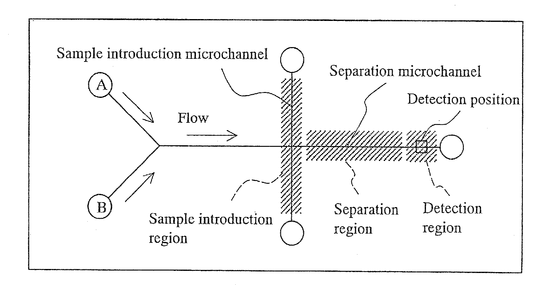
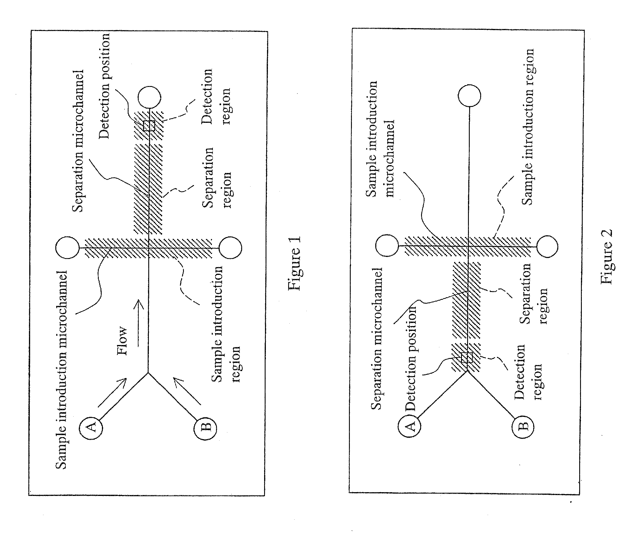
If the nucleic acid sample is exposed to the DNA melting temperature as it is being introduced, DNA separation will be initiated inside the sample introduction microchannel, interfering with optimal introduction of a uniform nucleic acid sample.

Method used


Image

  • Microchip electrophoresis method and device
  • Microchip electrophoresis method and device
  • Microchip electrophoresis method and device

Examples


example 1

[0063]A temperature control test was performed using an acrylic resin microchip (8.5 cm×5 cm, thickness 1 mm). K-type thermocouples were used as the temperature sensors and fixed to the center of the microchip top surface. The heaters were of the transparent conductive film type. The temperature controller was of the PID control type. Temperature measurements were taken with K-type thermocouples and recorded on a notebook computer.

[0064]When the preset temperature was raised from 48 to 50° C. in 1 degree increments in the test, the temperature distribution inside the microchip remained within ±2.5° C. of the preset temperature in each case. The same test was also performed with aluminum foil (0.1 mm thick) of the same size as the microchip inserted between the microchip and heaters to further reduce the temperature distribution of the microchip. As a result, the temperature distribution of the microchip was within ±1° C. of the preset temperature at each temperature level.

example 2

[0065]Two kinds of DNA with different nucleotide sequences are separated using a DGGE microchip with the flow shown in FIG. 3.

[0066]PCR products of the V3 regions of 16s rRNA genes obtains from two different kinds of Sphingomonas are used as the DNA samples. In the preparation of the DNA samples, the two different microorganisms are first cultured in liquid medium, and collected by centrifugation. The cells are mixed, and DNA is extracted from the mixture by the benzyl chloride method. This extracted DNA is subjected to PCR using universal primers targeting the V3 region of the 16S rRNA gene (forward: 5′-CGCCCGCCGC GCGCGGCGGG CGGGGCGGGG GCACGGGGGG CCTACGGGAG GCAGCAG-3′ (SEQ ID NO 1); reverse: 5′-ATTACCGCGG CTGCTGG-3′ (SEQ ID NO 2)), and the resulting PCR product is the final DNA sample. The forward primer is provided with a GC clamp.

[0067]A microchip having a microchannel 100 μm wide and 25 μm deep formed by photolithography on Pyrex™ glass (7 cm×3.5 cm) is used in the test. This mi...

example 3

[0070]A system was constructed for independently controlling the temperature of one part of a microchip in order to spatially control the temperatures of the regions for performing the sample introduction process, separation process and detection process. A microchip (8.5 cm×5 cm, thickness 1 mm), copper plate (1 cm×4 cm, thickness 3 mm), Peltier element (8 mm×8 mm), copper plate and heat sink were affixed together in that order, and a thermistor was attached as the heat sensor to the copper plate contacting the microchip. The Peltier element was connected to a fixed voltage power source, and the output was controlled with a temperature controller. The temperature behavior of the copper plate attached to the microchip was measured using a K-type thermocouple as the preset temperature was varied. As a result, the variation in temperature measurements over time was within ±0.6° C. when the preset temperature was 30° C., 40° C., 50° C. and 60° C.


PUM

PropertyMeasurementUnit
Temperatureaaaaaaaaaa

Abstract

An separation method comprising a temperature control process useful for microchip electrophoresis such as microchip DGGE is provided along with a device therefor.The present invention relates to a microchip electrophoresis method for separating double-stranded nucleic acids by means of differences in nucleotide sequence while maintaining a preset temperature, wherein the temperature during separation of double-stranded nucleic acids in an separation region comprising an separation microchannel is controlled to within ±2.5° C. of the preset temperature.

Description

BACKGROUND OF THE INVENTION[0001]The present invention relates to a microchip electrophoresis method and device for separating double-stranded nucleic acids by means of differences in nucleotide sequence at a preset temperature while maintaining that preset temperature.[0002]The following prior art is known for separation using capillaries or microchips. Japanese Patent Application 2001-515204 describes a microfluidic system equipped with a temperature-responsive energy source and a sensor connected functionally to a channel for determining the temperature of a fluid. Japanese Patent Application Laid-open No. 2003-117409 describes a device for microchemistry molded from heat-resistant plastic and provided with a temperature regulation means. Japanese Patent Application Laid-open No. 2004-279340 describes a microchip provided with a plurality of temperature sensors. International Patent Application WO2002 / 090912 describes a method for measuring the temperature of a liquid phase insid...

Claims


Application Information

Patent Timeline
IPC IPC(8): C07K1/26
CPCG01N27/44704G01N27/44791G01N27/44747
Inventor MORITA, TOMOYUKIMATSUMURA, TAKASHIMIYA, AKIKOYAMADA, HIROYUKI
Owner EBARA CORP
Learn More