Extreme low resistivity light attenuation anti-reflection coating structure in order to increase transmittance of blue light and method for maufacturing the same

Inactive Publication Date: 2009-12-03
INNOVATION & INFINITY GLOBAL
View PDF2 Cites 5 Cited by
  • Summary
  • Abstract
  • Description
  • Claims
  • Application Information

AI Technical Summary

Benefits of technology

[0010]One particular aspect of the present invention is to provide an extreme low resistivity light attenuation anti-reflection coating structure in order to increase transmittance of blue light. The process of manufacturing the extreme low resistivity light attenuation anti-reflection coating structure in high volume

Problems solved by technology

However, when we apply the metal base anti-reflection coating on a display screen to create a high EMI shielding effect for a computer monitor, or low reflection glass for an LCD or a PDP, there are some bottlenecks in the process for high volume mass production.
However, below 1.0 Ωm will lar

Method used


Image

  • Extreme low resistivity light attenuation anti-reflection coating structure in order to increase transmittance of blue light and method for maufacturing the same
  • Extreme low resistivity light attenuation anti-reflection coating structure in order to increase transmittance of blue light and method for maufacturing the same
  • Extreme low resistivity light attenuation anti-reflection coating structure in order to increase transmittance of blue light and method for maufacturing the same

Examples


Example

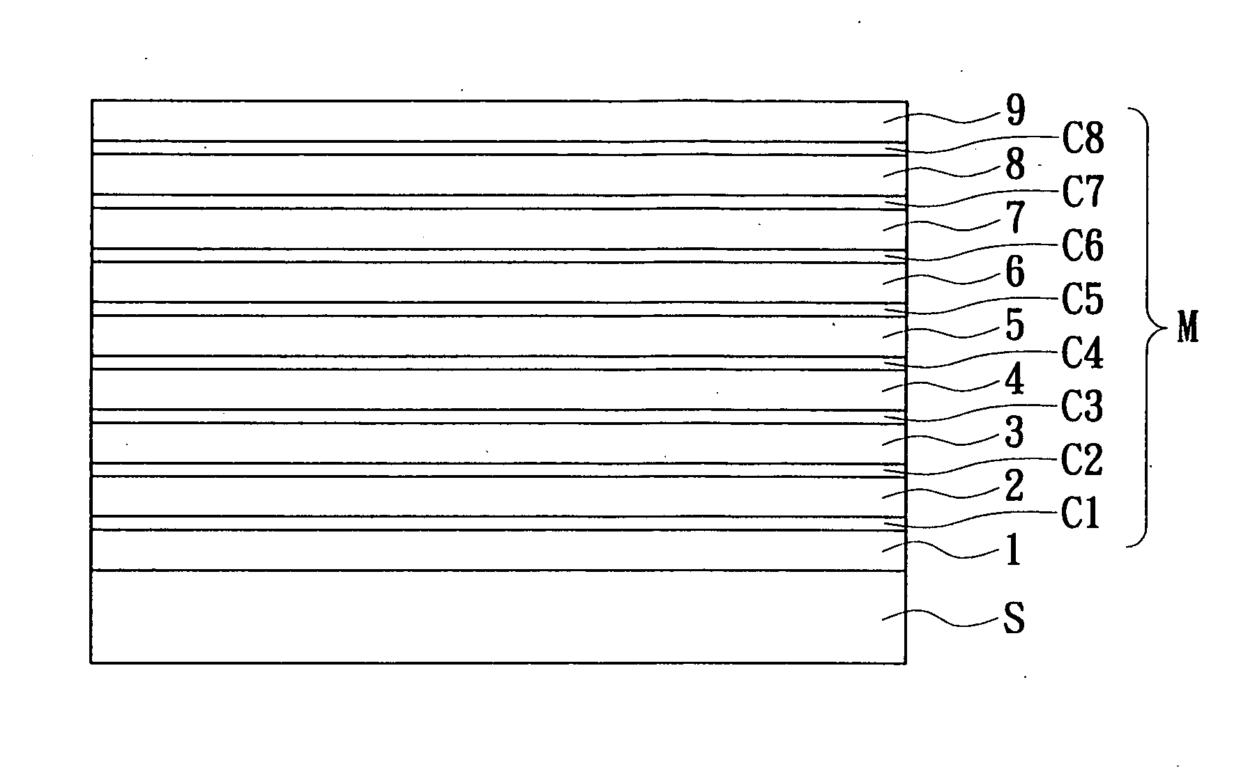
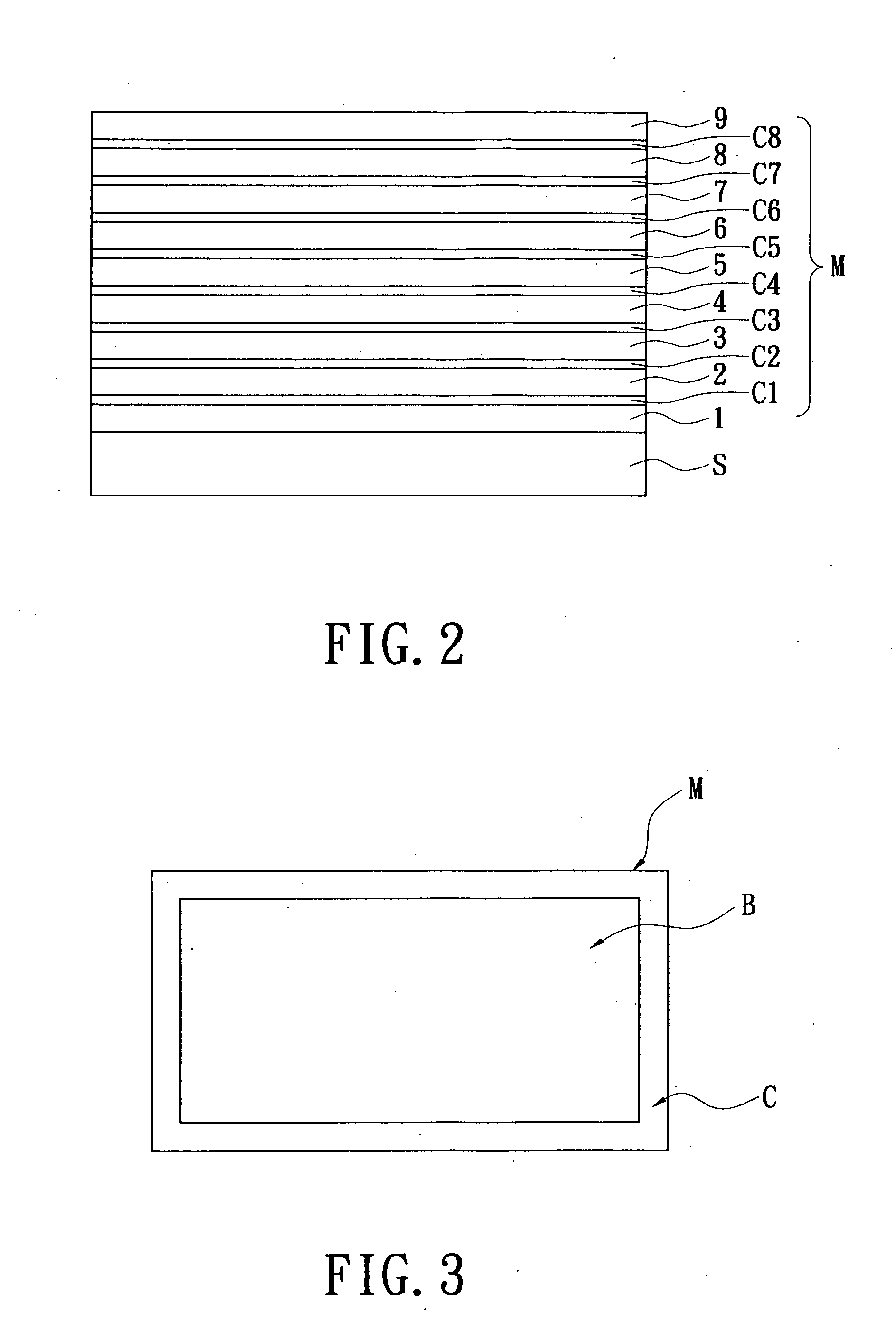
[0027]Referring to FIG. 2, the present invention provides an extreme low resistivity light attenuation anti-reflection coating structure in order to increase transmittance of blue light. The coating structure includes a substrate S and a coating module M.

[0028]The substrate S can be a plastic film or a glass. The coating module M can be a basic coating for a plasma display or a liquid crystal display.

[0029]Moreover, the coating module M includes a first coating layer 1 formed on a front surface of the substrate S, a first color conversion coating layer C1 formed on the first coating layer 1, a second coating layer 2 formed on the first color conversion coating layer C1, a second color conversion coating layer C2 formed on the second coating layer 2, a third coating layer 3 formed on the second color conversion coating layer C2, a third color conversion coating layer C3 formed on the third coating layer 3, a fourth coating layer 4 formed on the third color conversion coating layer C3...


PUM

PropertyMeasurementUnit
Fractionaaaaaaaaaa
Fractionaaaaaaaaaa
Thicknessaaaaaaaaaa

Abstract

An extreme low resistivity light attenuation anti-reflection coating structure in order to increase transmittance of blue light. The coating structure includes a substrate and a coating module. The coating module is formed on a front surface of the substrate and composed of a plurality of mixture coating layers, a plurality of Al-based oxide coating layers and a plurality of metal coating layers that are alternately stacked onto each other. Each mixture coating layer is composed of silicon carbide compound and Ti-based oxide.

Description

BACKGROUND OF THE INVENTION[0001]1. Field of the Invention[0002]The present invention relates to a coating structure and a method for manufacturing the same, and particularly relates to an extreme low resistivity light attenuation anti-reflection coating structure in order to increase transmittance of blue light and a method for manufacturing the same.[0003]2. Description of the Related Art[0004]It is well known that the conventional layer structure for an anti-reflection optical coating has a general principle. This general principle is that the surface layer of the optical coating should be a material that scores low on the refractive index such as SiO2, scoring 1.46 on the refractive index, or MgF2, scoring 1.38 on the refractive index. However, when we apply the metal base anti-reflection coating on a display screen to create a high EMI shielding effect for a computer monitor, or low reflection glass for an LCD or a PDP, there are some bottlenecks in the process for high volume ...

Claims


Application Information

Patent Timeline
IPC IPC(8): B32B15/20B05D1/36B05D5/12
CPCC03C17/36C03C17/3618C03C17/3634C03C17/3639Y10T428/265C03C2217/734G02B1/115Y10T428/12667Y10T428/24975C03C17/3657
Inventor CHANG, CHENG-CHIEHLIU, HSIU-FENGKUO, PI-JUI
Owner INNOVATION & INFINITY GLOBAL
Why Eureka
Try Eureka