Spinal fusion methods and devices

a spine and fusion technology, applied in the field of spine fusion methods and devices, can solve the problems of back pain, rupture or degeneration of intervertebral discs, and middle-aged working population's disability, and achieve the effects of reducing bone formation, promoting and limiting bone growth, and minimizing undesirable migration of osteoinductive composition

Inactive Publication Date: 2009-12-03
WARSAW ORTHOPEDIC INC
View PDF19 Cites 2 Cited by
  • Summary
  • Abstract
  • Description
  • Claims
  • Application Information

AI Technical Summary

Benefits of technology

[0011]It has been discovered that blending osteoinductive compositions with a slow release carrier can effectively reduce bone formation in undesired locations during spinal fusion procedures. For example the slow release carrier can inhibit migration of the entrained osteoinductive composition to tissue adjacent the treatment site, for example, sites of hematoma, scar tissues, or other fibrous tissues that are a distance from, or adjacent to, the desired site for fusion. Accordingly, one aspect of the invention provides methods for fusing adjacent vertebrae, and otherwise localizing bone growth, in an interbody fusion procedure. The method is particularly advantageous for treatment sites that already exhibit a localized hematoma or scar tissues or exhibit a clinical predisposition for such. During the disc space preparation, a hematoma site or scar tissue site can be exposed or evaluated for a predisposition for bone tissue growth induced by a diffusible osteoinductive factor. In one embodiment, an osteoinductive composition and a carrier composite can be formulated to promote and limit bone growth to a desired treatment site. In another embodiment, an implant can be advantageously formulated and configured to retain an osteoinductive composition. The osteoinductive composition is therefore provided to and carried by the implant minimizing undesirable migration of the osteoinductive composition from the implant.
[0013]A composition for use in the invention includes a carrier and an effective amount of an osteoinductive material or an osteoinductive factor. The osteoinductive material can be entrapped or entrained within the carrier. The carrier is preferably substantially impermeable to efflux of the osteoinductive factor. In one embodiment, the osteogenic material is released from the carrier as the carrier is degraded or resorbed. In one embodiment, bone formation can be substantially confined to the original volume or space occupied by the carrier, osteogenic material. Migration of the osteogenic material to the hematoma site or scar tissue site is significantly reduced or eliminated. In another embodiment of the invention, the carrier is a resorbable cement and the osteogenic material is an osteoinductive factor or bone morphogenetic protein.

Problems solved by technology

Back pain affects millions of individuals and is a common cause of disability for the middle-aged working population.
A frequent cause of back pain is rupture or degeneration of intervertebral discs.
Spinal discs may be displaced or damaged due to trauma; disease, or aging.
The extruded nucleus pulposus may press on a spinal nerve, which may result in nerve damage, pain, numbness, muscle weakness and paralysis.
Intervertebral discs may also deteriorate due to the normal aging process or disease.
As a disc dehydrates and hardens, the disc space height will be reduced leading to instability of the spine, decreased mobility and pain.
Collapse of the disc space can cause instability of the spine, abnormal joint mechanics, premature development of arthritis or nerve damage, in addition to severe pain.
In certain instances, it is possible that the osteoinductive material that includes an osteoinductive factor may diffuse, or otherwise migrate, from the implant into undesired locations, which may result in bone formation in these locations.
The can be an increased risk of hematoma formation with posterior lumbar interbody fusion (PLIF) or transforamiinal lumbar interbody fusion procedure, because the blood released during these procedures can pool in the spinal canal or foramen space.

Method used


Image

  • Spinal fusion methods and devices
  • Spinal fusion methods and devices
  • Spinal fusion methods and devices

Examples


example 1

Single-level Posterolateral Fusion in Rhesus Monkeys

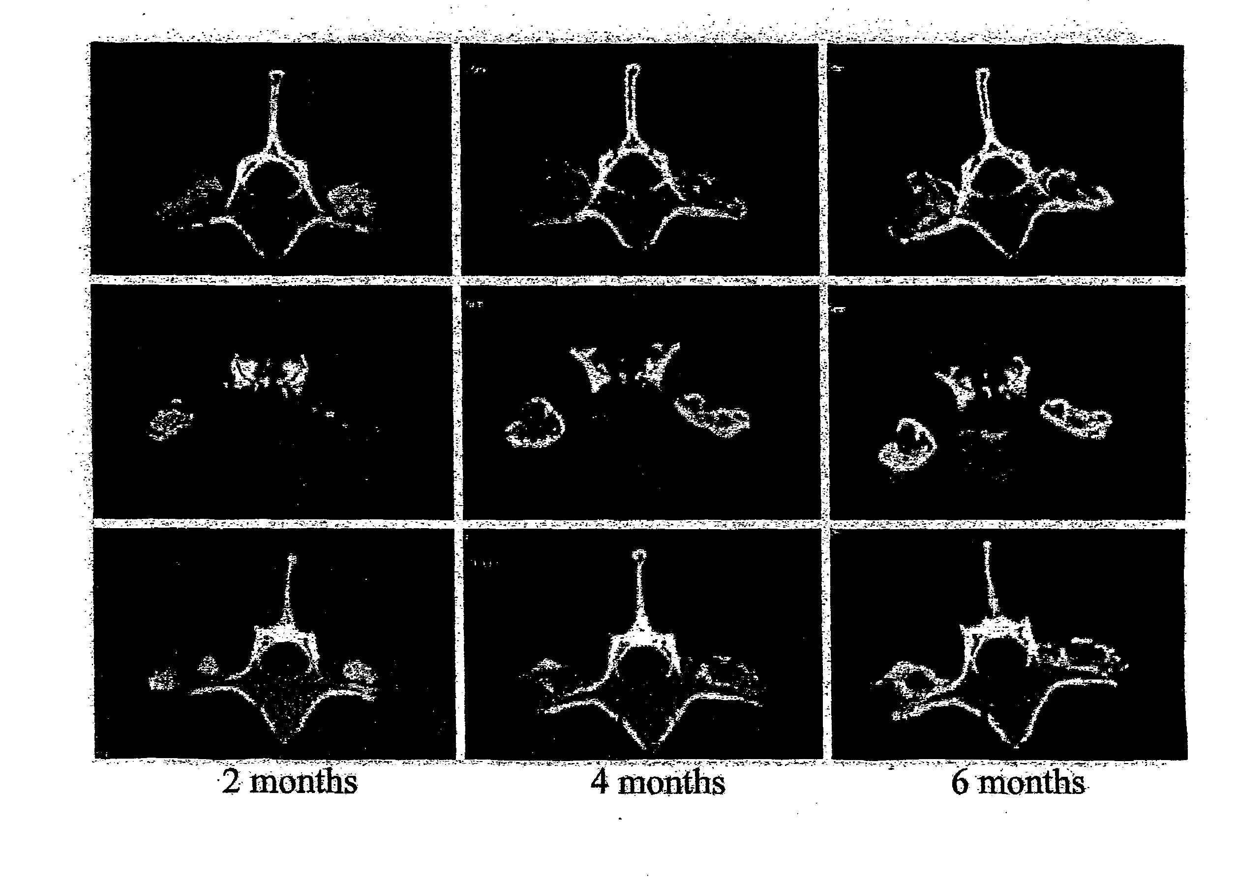
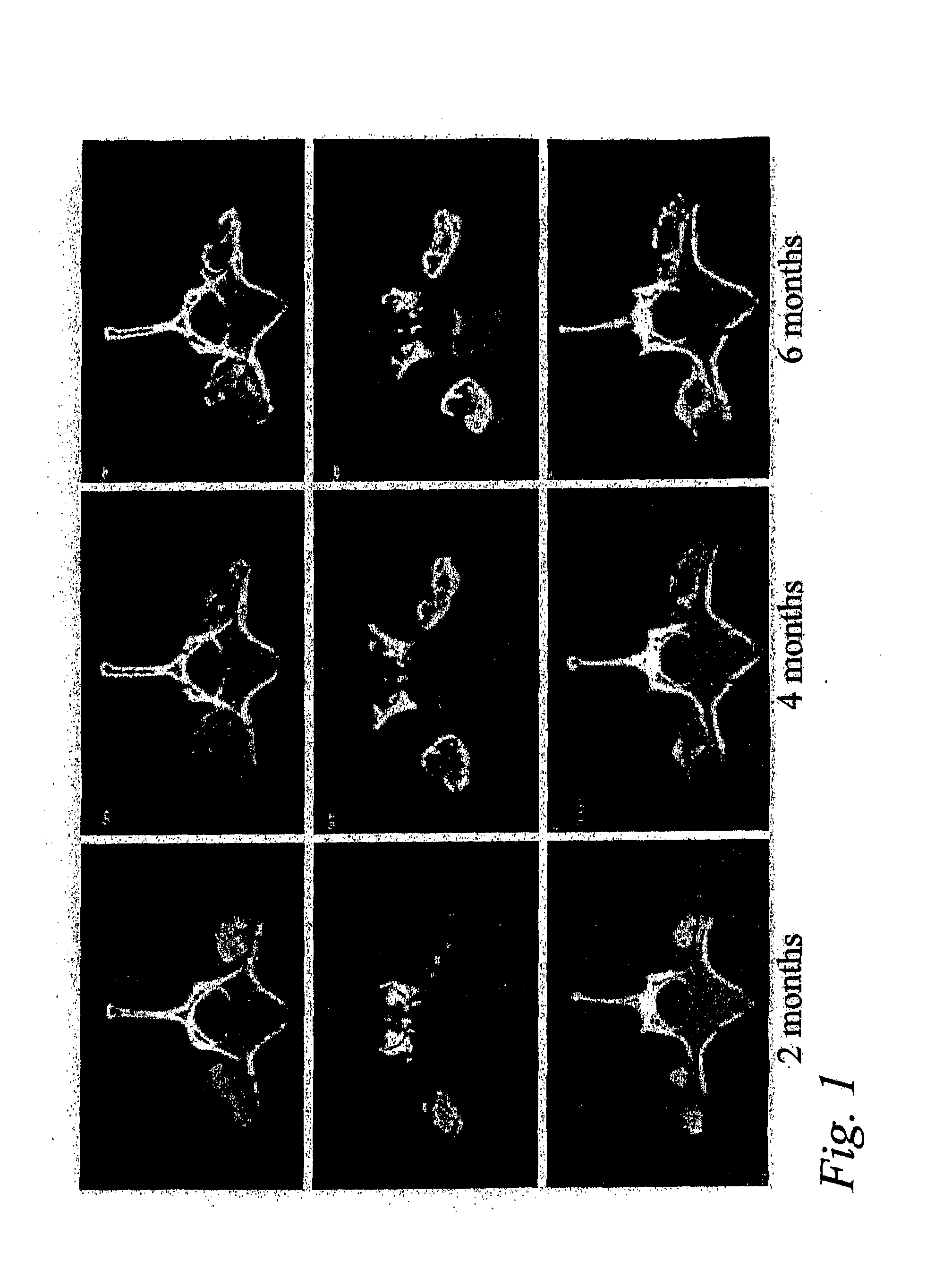
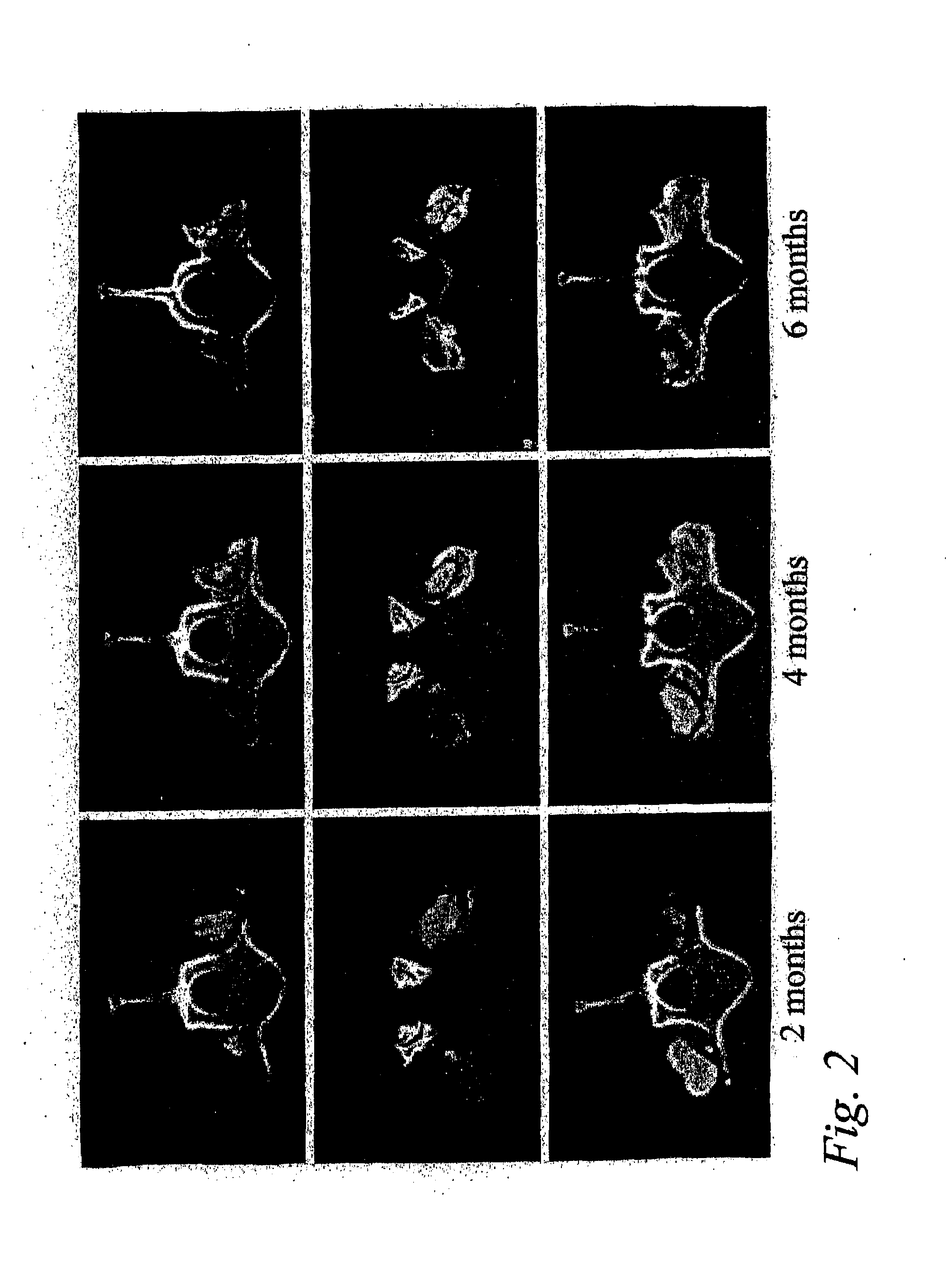
[0048]This example shows that posterolateral fusions performed in Rhesus monkeys with the bone substitute compositions described herein resulted in new bone formation that was confined to the volume occupied by the bone substitute compositions.

Animals and Experimental Design

[0049]Posterolateral transverse process fusions in 2 groups of 2 Rhesus monkeys were performed. One of the groups received rhBMP-2 in a carrier of standard α-bone substitute material (standard α-BSM®), a commercially available calcium phosphate cement purchased from Etex Corp., Cambridge, Mass. This standard material has a microporosity of 40%. The other group received rhBMP-2 in a carrier of modified α-BSM® (a bone substitute material from Etex with a porosity greater than 40%). In this second group, the left side of the spine was treated with the rhBMP-2 in a carrier of Δ-BSM® having 80% porosity (the porosity was increased by increasing the liquid content) an...

example 2

Pharmacokinetic Study of the Release of rhBMP-2 From α-BSM and ACS

[0053]The release kinetics for rHBMP-2 from α-BSM and ACS evaluated in a rabbit ulna osteotomy. A 125I-rhBMP-2 / α-BSM or 125IrhBMP-2 / ACS product was surgically implanted in a rabbit ulna osteotomy. Assessment of the radioactivity at the implant site were made as soon as possible following surgery. Additionally assessments were made periodically thereafter including at 1, 2, 3, 4, 7, 14 and 21 days after surgery.

[0054]The rhBMP-2 was radiolabeled with 125I using the iodogen technique. The following a typical procedure. An 80 μg / mL solution of iodogen reagent (Pierce, Rockford, Ill.) was prepared in chloroform. An aliquot of this solution (50 μL) was placed into a micro-eppendorf tube and evaporated to dryness under a gentle stream of nitrogen. To this tube was added 30 μg of rhBMP-2, sufficient MFR 00842 buffer to bring the volume up to 50 μL, and 1-2 mCi of carrier-free 125I (Dupont NEN Research Product, Boston Mass.)....


PUM

PropertyMeasurementUnit
temperatureaaaaaaaaaa

Abstract

Methods, devices and compositions for fusing adjacent vertebrae, and otherwise localizing bone growth, are provided. In one form of the invention, a method for fusing adjacent vertebrae includes preparing a disc space for receipt of an intervertebral disc implant in an interwertebral disc space between adjacent vertebrae, inserting the implant into the intervertebral disc space and providing an osteoinductive composition that includes an osteoinductive factor in a pharmaceutically acceptable carrier. The carrier is advantageously substantially impermeable to efflux of the osteoinductive factor and is released as the carrier is resorbed or biodegraded. Preferred carriers include a hardened, resorbable carrier, such as a calcium phosphate cement that retains at least about 50% of the osteoinductive factors greater than about 2 days. Preferred osteoinductive factors are growth factors and include bone morphogenctic proteins and LIM mineralization proteins. In alternative forms of the invention, the method may be performed without utilization of a load-bearing spinal implant by disposing the osteoinductive composition in the disc space. The method is advantageously performed on lumbar vertebrae by a posterior approach. Intervertebral fusion devices and methods for their preparation are also provided.

Description

CROSS-REFERENCE TO RELATED APPLICATION[0001]The present application claims the benefit of U.S. Provisional Application Ser. No. 60 / 424,794, filed on, Oct. 24, 2000, which is hereby incorporated by reference in its entirety.BACKGROUND OF THE INVENTION[0002]The present invention relates generally to methods and devices for stabilizing the spine. More specifically, the invention provides methods and devices for fusing adjacent vertebrae and for localizing spinal bone growth.[0003]Back pain affects millions of individuals and is a common cause of disability for the middle-aged working population. A frequent cause of back pain is rupture or degeneration of intervertebral discs.[0004]Intervertebral discs, located between the endplates of adjacent vertebrae, stabilize the spine, distribute forces between vertebrae and cushion vertebral bodies. An intervertebral disc includes the nucleus pulposus, a gelatinous component that is surrounded and confined by an outer, fibrous ring, called the a...

Claims


Application Information

Patent Timeline
Patent Type & Authority Applications(United States)
IPC IPC(8): A61K38/16A61K38/18A61B17/58A61B17/56A61F2/00A61F2/02A61F2/28A61F2/44A61F2/46A61L27/00A61L27/12A61L27/18A61L27/22A61L27/24A61L27/54A61L27/58
CPCA61B17/58A61B2017/564A61F2/442A61F2/4455A61F2002/2817A61F2002/30062A61L2430/02A61F2002/4635A61F2210/0004A61F2210/0014A61F2310/00293A61F2310/00353A61F2310/00365A61F2002/30092A61L2430/38A61P19/08
Inventor MCKAY, WILLIAM F.
Owner WARSAW ORTHOPEDIC INC
Why Eureka
Try Eureka