Trench schottky with multiple epi structure

a technology of epi-structure and schottky, which is applied in the direction of basic electric elements, semiconductor devices, electrical equipment, etc., to achieve the effects of reducing forward voltage drop, reducing doping concentration, and increasing doping concentration

Inactive Publication Date: 2009-12-17
FORCE MOS TECH CO LTD
View PDF12 Cites 38 Cited by
  • Summary
  • Abstract
  • Description
  • Claims
  • Application Information

AI Technical Summary

Benefits of technology

[0010]Briefly, in a preferred embodiment, the present invention discloses a Schottky barrier rectifier with double epitaxial layer with lower doping concentration near trench bottom and higher doping concentration above the trench bottom. The upper epitaxial layer doping concentration can be monitored by Hg-CV method while the lower epi layer doping concentration is able to be calculated by measuring total doping concentration of two epitaxial layers using 4PP (Four Point Probe) method, and then subtracting the upper doping concentration measured by Hg-CV method. The substrate comprises a highly doped N+ region, on which epitaxial layer is grown. In the prior art, the concentration of the epitaxial layer is linearly increased from the second face to the interface of the epitaxial layer and N+ region, which results in some problems as we discussed above. In the present invention, the epitaxial layer is designed to comprise two values of concentrations. The concentration remains the same from the second face to the bottom of the trench and from the bottom of the trench to the interface of the epitaxial layer and the N+ region, respectively. Meanwhile, the former concentration is higher than the latter one. This double epi design has the advantage of maintaining targeted BV near trench bottom due to the lower doping concentration, while forward voltage drop is reduced with higher doping concentration in drift region between trenches. In another embodiment, an improvement is designed on base of the first embodiment. Near the surface of the epitaxial layer, shallow boron or BF 2 Ion Implantation is introduced to reduce the reverse leakage current between anode and cathode. As the concentration is lower near the surface of the epitaxial layer, the Schottky barrier height is increased, thus leading to the reduction of reverse leakage current between anode and cathode. Besides this, the concentration is the same from the shallow implanted layer to the bottom of the trench and from the bottom of the trench to the interface of the epitaxial layer and the N+ region, respectively, which maintain the advantages of the first embodiment. In another embodiment, there is a triple epitaxial layers in the rectifier. A thin epitaxial layer near the surface of the epitaxial layer is uniformly doped with a low concentration. From the thin layer to the bottom of the trench, the concentration is higher than the above thin layer and also is uniform as the former two embodiments. From the bottom of the trench to the interface of the epitaxial layer to the N+ region, the concentration is lower again and the same as the concentration of the thin layer. This triple epitaxial layers design has the advantages of that of both two embodiments discussed above. And in all three embodiments, the oxide layer around the trench is greater than about 1000 Å, and that will contribute to an increase in the reverse breakdown voltage.

Problems solved by technology

In the prior art, the concentration of the epitaxial layer is linearly increased from the second face to the interface of the epitaxial layer and N+ region, which results in some problems as we discussed above.

Method used


Image

  • Trench schottky with multiple epi structure
  • Trench schottky with multiple epi structure
  • Trench schottky with multiple epi structure

Examples


third embodiment

[0022]Please refer to FIG. 6 for this invention, still the same structure of the rectifier, the concentration comprises three values of distribution. As shown in the profile of FIG. 6. Instead of the shallow Boron or BF 2 Ion Implantation, a thin layer near the surface of drift region 12d is uniformly doped with a low concentration. From the thin layer to the bottom of the trench and from the bottom of the trench to the first face 12a, the concentration remains the same, respectively, as discussed in the above two embodiments. In the triple epitaxial model, as shown is the profile, the concentration of the middle portion is the higher than the other two portions. This kind of distribution keeps the advantages of above two embodiments, which are reducing the reverse leakage current due to higher barrier height, and reducing forward voltage drop with higher doping concentration in drift region between trenches, and maintaining targeted BV near trench bottom with lower doping concentra...

second embodiment

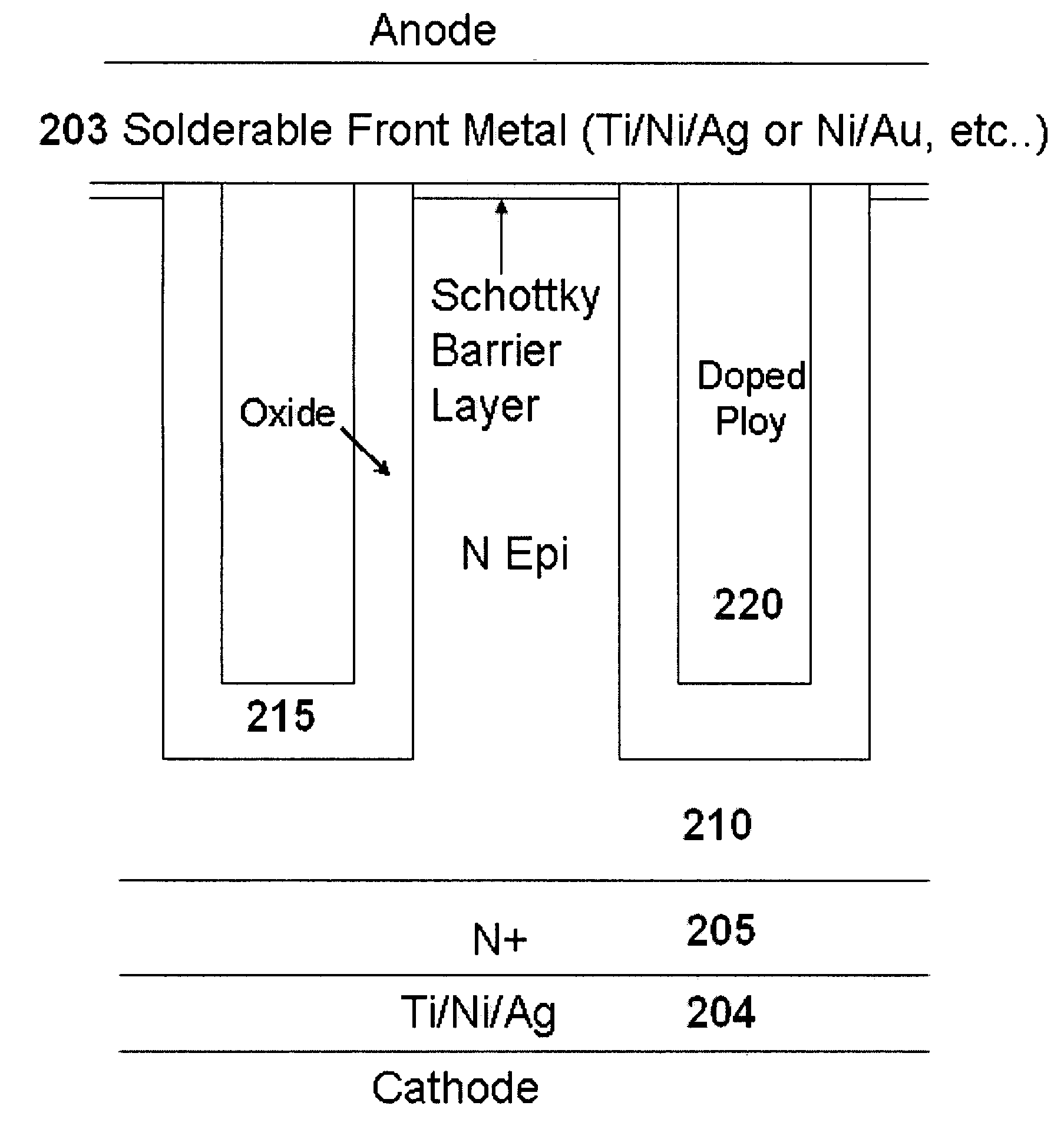
[0024]In FIG. 7C, the process continues with the removing of oxide layer by Wet Oxide Etch. A Boron or BF 2 Ion Implantation process is followed for the second embodiment to form the shallow concentration distribution. Referring to FIG. 7D, a layer of high work function metal such as Mo, Pt, or Ni / Pt or NiCr / Pt, etc, is deposed, then an elevated temperature (500 C) is applied to form silicide. Referring to FIG. 7E, the layer of high work function metal is removed with Aqua Regia, and followed the deposition of solderable front metal 203, such as Ti / Ni / Ag or Ni / Au, ect. Beneath the cathode region 205, a layer of back metal 204 is deposed to form the cathode electrode.


PUM


Abstract

A trench Schottky barrier rectifier includes an cathode electrode at a face of a semiconductor substrate and an multiple epitaxial structure in drift region which in combination provide high blocking voltage capability with low reverse-biased leakage current and low forward voltage. The multiple structure of the drift region contains a concentration of first conductivity dopants therein which comprises two or three different uniform value from a Schottky rectifying junction formed between the anode electrode and the drift region. The thickness of the insulating region (e.g., SiO2) in the MOS-filled trenches is greater than 1000 Å to simultaneously inhibit field crowing and increase the breakdown voltage of the device. The multiple epi structure is preferably formed by epitaxial growth from the cathode region and doped in-situ.

Description

FIELD OF THE INVENTION[0001]This invention relates generally to the cell structure, device configuration and fabrication process of rectifiers. More particularly, this invention relates to novel and improved metal-semiconductor rectifying devices with a higher breakdown voltage, a lower forward voltage drop and lower reverse leakage characteristics and the methods of forming these devices with such characteristics.BACKGROUND[0002]Schottky barrier rectifiers are used extensively as output rectifiers in switching-mode power supplies and in other high-speed power switching applications, such as motor drivers, for carrying large forward currents and supporting reverse blocking voltage of up to 100 Volts. Schottky barrier rectifiers are also applicable to a wide range of other applications such as those illustrated in FIG. 1. As is well known to those having skill in the art, rectifiers exhibit low resistance to current flow in a forward direction and a very high resistance to current fl...

Claims


Application Information

Patent Timeline
Patent Type & Authority Applications(United States)
IPC IPC(8): H01L29/47
CPCH01L29/0611H01L29/8725H01L29/872
Inventor HSIEH, FU-YUAN
Owner FORCE MOS TECH CO LTD
Why Eureka
Try Eureka