Apparatus and process for production of liquid fuel from biomass

a technology of biomass and apparatus, which is applied in the field of apparatus and process for the production of liquid fuel from biomass, can solve the problems of low calorific value, low biomass recognition, and inability to obtain the synthetic gas required for the production of liquid fuel with a high calorific value, so as to improve the yield of synthesis liquid fuel gas, prevent the effect of getting complicated and simplifying the cooling system

Inactive Publication Date: 2009-12-24
NAGASAKI INSTITUTE OF APPLIED SCIENCE
View PDF5 Cites 27 Cited by
  • Summary
  • Abstract
  • Description
  • Claims
  • Application Information

AI Technical Summary

Benefits of technology

[0050]According to the present invention, by serially arranging a plurality of reactors, high yield of synthesis liquid fuel gas is obtained since the temperature of methanol synthesis is maintained continuously in spite of a low pressure operation, and also the cooling system is simplified so as to prevent getting complex in spite of the existence of the plurality of reactors. Therefore, an improved apparatus is provided.
[0051]By the biomass gasification reaction apparatus of the present invention, synthetic gas suitable for the synthesis of liquid fuel gas can be obtained. This provides an effect according to which the liquid fuel yield is increased to improve the stability and reliability in the operation of the entire apparatus. Furthermore, synthetic gas contains higher content of carbon monoxide and carbon dioxide by adding hydrogen gas obtained by water electrolysis.

Problems solved by technology

First, biomass has not been highly recognized until recently.
Secondly, since biomass includes oxygen, the calorific value is low and thus such synthetic gas required for the production of liquid fuel could not be obtained that had a high calorific value and that included H2 at a high content ratio.
However, the gasification methanol synthesis has not reached a level at which methanol is synthesized efficiently.
The reason is that biomass has a low calorific value as described above, thus failing to provide synthetic gas having a high calorific value required for the methanol synthesis.
Furthermore, due to the longitudinal layout in which the reactors are arranged in the longitudinal direction from the top to bottom, an exchange of catalysts has required the disassembly of reactors in all stages and thus has required a long-time maintenance and thus an inconvenience also has been caused in the operation schedule.
Furthermore, due to the layout in which temperature controlling devices are parallely arranged in all stages, a disadvantage has been caused that the resultant apparatus is complicated.
If these concentrations are low, methanol gas cannot be synthesized at a high yield.
Furthermore, only synthetic gas obtained from biomass cannot provide a sufficient amount of hydrogen to synthesize methanol from carbon dioxide.

Method used


Image

  • Apparatus and process for production of liquid fuel from biomass
  • Apparatus and process for production of liquid fuel from biomass
  • Apparatus and process for production of liquid fuel from biomass

Examples


first embodiment

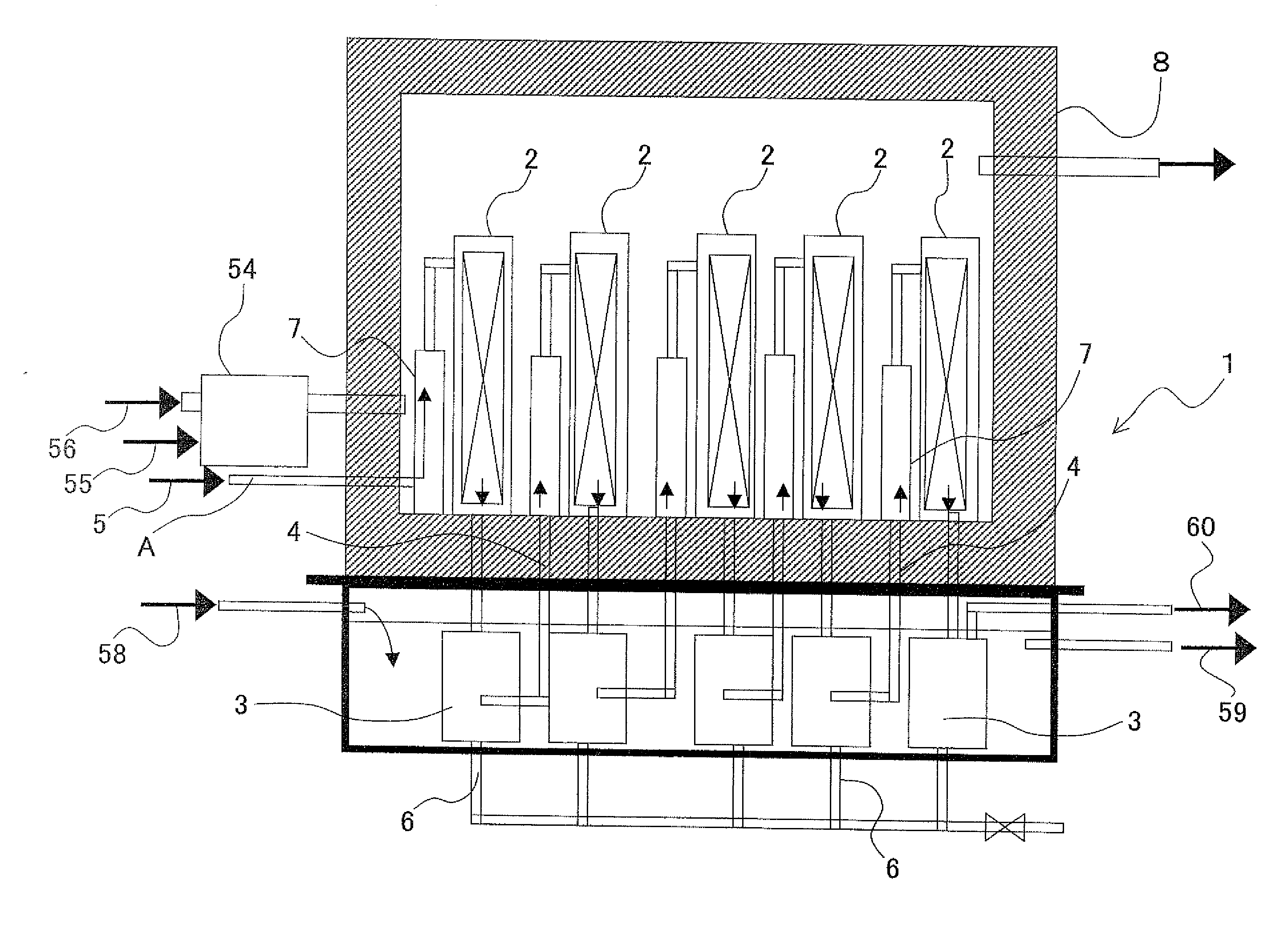
[0085]FIG. 1 schematically illustrates a multistage liquid fuel synthesis basic experiment apparatus that is the first embodiment according to the present invention. The liquid fuel synthesis apparatus is structured to include a plurality of reactors 2 generally arranged in 3 stages to 10 stages. In the shown example, the liquid fuel synthesis apparatus is composed of the reactors 2 in 5 stages. These reactors 2 are arranged serially with regard to the flow of gas.

[0086]The upstream-side of the reactor 2 is connected to a synthetic gas supply pipe 4 and the downstream-side is connected to a reaction gas derivation pipe 5 to be linked to a cooler 3. Synthetic gas, which is synthesis raw material of liquid fuel, is supplied from the synthetic gas supply pipe 4 to the reactor 2. The reactor 2 at the most upstream-side is linked to a synthesis raw material gas supply line A and receives the supply of synthetic gas. In the case of methanol synthesis, the reactor 2 for synthesizing liquid...

second embodiment

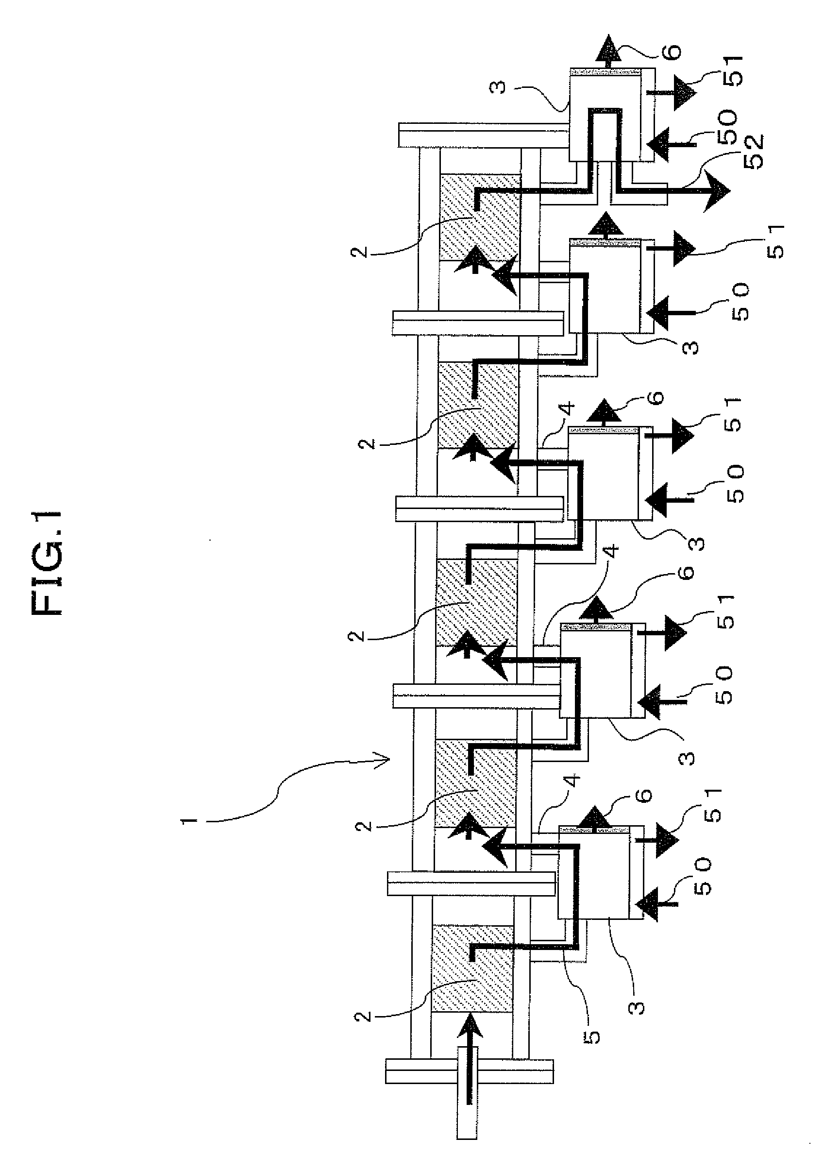
[0102]Next, the liquid fuel synthesis apparatus having the main function of the present invention is shown in FIG. 3. The liquid fuel synthesis apparatus is composed of: the reactors 2 including therein catalysts and being made of stainless steel; the coolers 3 for cooling synthesized liquid fuel gas to extract liquid methanol; and temperature adjustment means 7 for adjusting, by heat exchange, the synthetic gas including an unreacted gas component left after the collection of liquid methanol to have a reaction temperature suitable for the synthesis. These members are arranged in a serial manner along the gas flow direction at multiple stages. The temperature adjustment means 7 and the reactors 2 are stored in a constant temperature room 8 having a heat insulating structure surrounded by a heat insulating material.

[0103]The coolers 3 on the other hand are stored in a cooling bath 53 positioned at the lower side of the constant temperature room 8.

[0104]Although this example shows a l...

third embodiment

[0112]Next, FIG. 5 illustrates a configuration example of the entire liquid fuel production apparatus for carrying out the present invention. Specifically, the liquid fuel production apparatus is composed of: a biomass supply hopper 205; a gasification reaction apparatus 201; and the liquid fuel synthesis apparatus 1. The gasification reaction apparatus 201 includes therein the secondary gasification reaction pipe 203 and the primary gasification reaction room 202 having a gasification agent supply line 303 linked to the secondary gasification reaction pipe 203. The liquid fuel synthesis apparatus 1 is structured, as described above, so that the reactors 2 (not shown in FIG. 5) and the coolers 3 (not shown in FIG. 5) are arranged in a serial manner. The reactor 2 and the cooler 3 are connected to each other via the synthetic gas supply pipe 4 (not shown in FIG. 5) and the reaction gas derivation pipe 5 (not shown in FIG. 5). The cooler 3 (not shown in FIG. 5) includes the liquid fu...


PUM

PropertyMeasurementUnit
pressureaaaaaaaaaa
pressureaaaaaaaaaa
pressureaaaaaaaaaa

Abstract

The liquid fuel synthesizing apparatus (1) for efficient synthesis of liquid fuel from biomass, such as plant for a raw material, comprised of reactors (2) with a catalyst incorporated therein, coolers (3) for cooling of synthesized gaseous matter and extracting of liquid fuel, and temperature adjustment means (7) for regulating by heat exchange any unreacted gas after recovery of liquid fuel to reaction temperature suitable for liquid fuel gas synthesis, wherein the reactors, the coolers and the temperature adjustment means are arranged multistage inline-straightly along gas flow. The temperature adjustment means (7) and the reactors (2) are disposed in the constant temperature room (8) in parallel. The coolers (3) are disposed apart from the constant temperature rooms (8).

Description

TECHNICAL FIELD[0001]The present invention relates to an apparatus and a production process for synthesizing liquid fuel from biomass such as plants as a raw material.TECHNICAL BACKGROUND[0002]When considering the shortage and depletion of oil resources and the global warming issue mainly due to CO2, the importance of the selection and development of the substitutes cannot be overstressed. Since a long-term forecast shows that an enormous amount of substitutes is required, large expectations have been placed, from a quantitative viewpoint, on the production of synthetic fuel made from biomass as a raw material.[0003]As in a case where natural gas and coal are used as raw material, liquid fuel (e.g., methanol, DME (dimethyl ether), or hydrocarbon by F-T (Fischer-Tropsch) process) can be obtained from synthetic gas (H2+CO) obtained by using biomass as a raw material to gasify the material. These liquid fuels synthesized from biomass have advantages, including: (1) these fuels are obta...

Claims


Application Information

Patent Timeline
Patent Type & Authority Applications(United States)
IPC IPC(8): C07C27/20B01J19/00
CPCC10G2/32
Inventor SAKAI, MASAYASUMURAKAMI, NOBUAKITAKEGAWA, TOSHIYUKIKAWASHIMA, HACHIRO
Owner NAGASAKI INSTITUTE OF APPLIED SCIENCE
Why Eureka
Try Eureka