Anti-Reflection Structure Body, Method Of Producing The Same And Method Of Producing Optical Member

a structure body and anti-reflection technology, applied in the direction of optical elements, identification means, instruments, etc., can solve the problems of complicated procedure, troublesome method, and posed exfoliation of coatings, and achieve the effect of easy production

Active Publication Date: 2009-12-31
TOKYO UNIVERSITY OF SCIENCE
View PDF5 Cites 13 Cited by
  • Summary
  • Abstract
  • Description
  • Claims
  • Application Information

AI Technical Summary

Benefits of technology

[0027]According to the invention, an anti-reflection structure body which is easily produced, capable of achieving an anti-reflection effect near to non-reflection, and capable of providing the minute structure even to a member having a high melting point such as quartz glass or the like by transfer and a method of producing the same as well as a method of producing an optical member using the same can be provided.

Problems solved by technology

However, according to this method, it is necessary to carry out the coatings several times for individual members, and therefore, not only is the method troublesome, but a problem of exfoliation of the coating is posed.
Although as a method of forming such a minute structure, for example, there is known a method of patterning a surface of a substrate of quartz glass or the like by photolithography, an electron beam or the like, this procedure is complicated and it is difficult to form a minute structure at a surface having a large area.
However, according to this method, for respective substrates, a material that forms the mask is adhered as small particles by sputtering, thereafter, dry etching is carried out, and therefore, not only is productivity invariably low, but it is difficult to form an anti-reflection structure at a substrate having a large area.
However, according to the above-described method, when the mold is produced, at least formation of the nuclei and growth of acicular crystals are needed, and therefore, the process becomes complicated.
Further, although the produced mold can repeat molding for a member made of a resin, the mold cannot repeatedly be used for a member having a high melting point such as quartz glass or the like.

Method used


Image

  • Anti-Reflection Structure Body, Method Of Producing The Same And Method Of Producing Optical Member
  • Anti-Reflection Structure Body, Method Of Producing The Same And Method Of Producing Optical Member
  • Anti-Reflection Structure Body, Method Of Producing The Same And Method Of Producing Optical Member

Examples


examples 2 through 12

[0094]The surface processing of the glassy carbon substrate is carried out by changing at least one of the acceleration voltage, the gas flow rate and the processing time from those of Example 1.

[0095]Processing conditions of Example 1 through Example 12 are summarized in Table 1.

TABLE 1gas flowcurrentexampleaccelerationrateprocessingdensityprocessingNo.voltage [V]extractor[SCCM]time [min][mA / cm2]depth [μm]1100002.0102.072.92100002.0601.9515.8375002.0101.803.1475002.0601.8019.5550002.051.200.73650002.0101.231.6750002.0301.205.1850002.0451.208.6950001.4601.2910.51050003.0600.969.711250102.0601.14—12100102.0601.20—

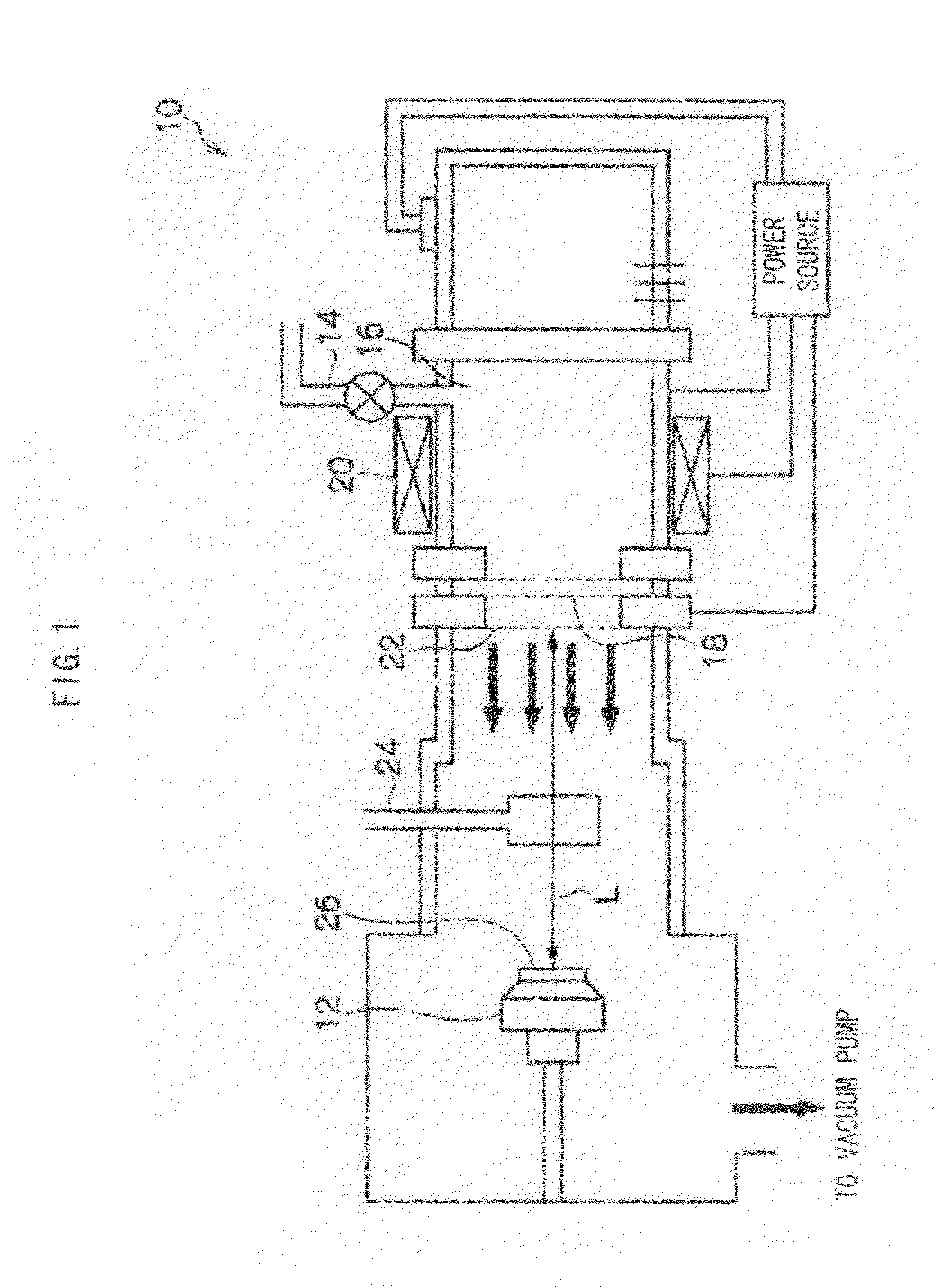
[0096]In Examples 11 and 12, the extractor 18 is used and scale 10 of the extractor 18 corresponds to 300 V. The current density is a measured value at a Faraday cup 24.

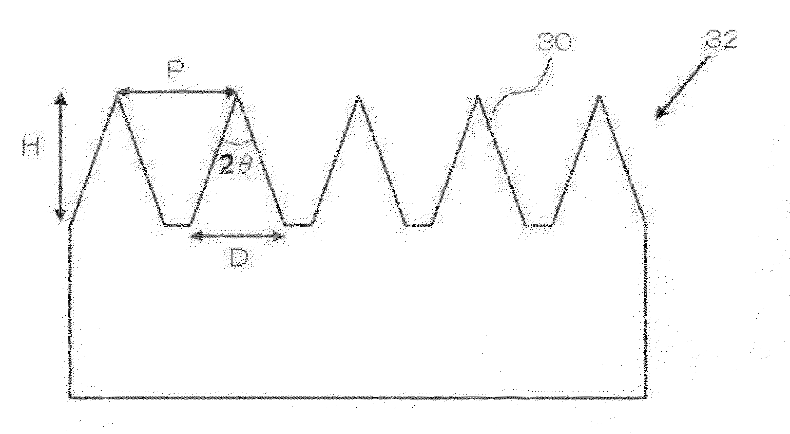
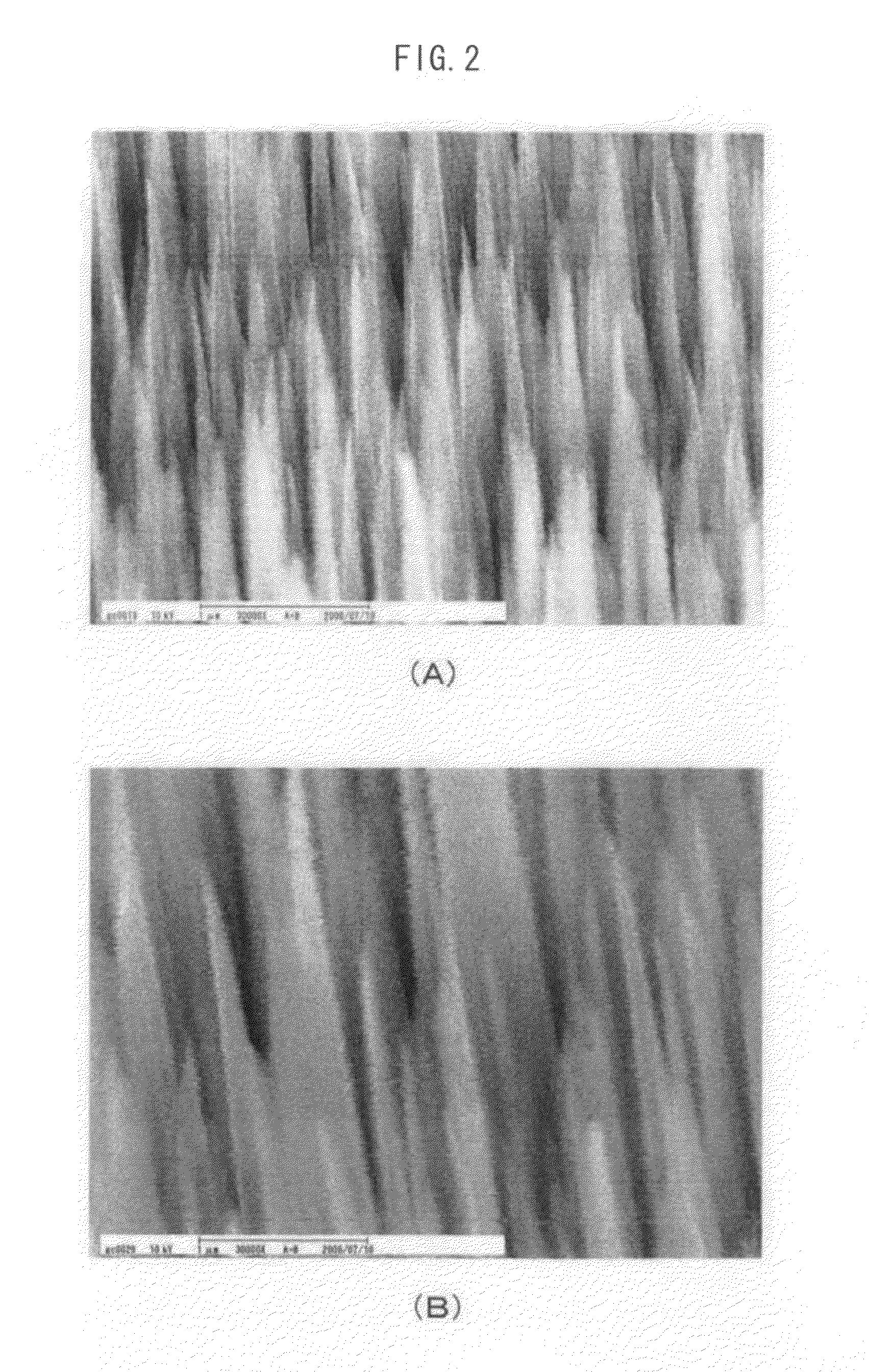
[0097]“Processing depth” in Table 1 is a depth of a recess portion formed at a surface of the substrate by irradiating an ion beam, and an anti-reflection structure formed of a cluster of projections of acicu...

example 1

Transfer Example 1

[0103]An anti-reflection structure is formed by processing one face of a glassy carbon (GC) substrate (length and width: 10×10 mm, thickness: 1 mm) by using ECR under the following condition.

[0104]Acceleration voltage: 500 [V]

[0105]Processing time: 30 [min]

[0106]Extractor: 0

[0107]Gas kind: oxygen

[0108]Gas flow rate: 3.0 [SCCM]

[0109]Ion emission: 13.1 [mA]

[0110]Rotation speed of holder: 0 [rpm]

[0111]Microwave output: 100 [W]

[0112]Current density: 1.67 [mA / cm2]

[0113]Distance (L) between beam extracting electrode and GC substrate: 11.7 cm

[0114]A face at which the anti-reflection structure is formed by the above-described processing is coated by a fluoro-resin coating agent (OPTOOL (registered trade mark), made by Daikin Industries Ltd., 0.1%) as a mold release agent, thereafter, spin-coated with a photo-curable resin (PAK-01, made by Toyo Gosei Co., Ltd.) thereon. The face coated with PAK-01 is pressed to a slide glass, and transfer is carried out by curing PAK-01 by ...

example 2

Transfer Example 2

[0122]Transfer is carried out by using SOG (Spin on Glass, made by Honeywell International Inc., Accuglass (registered trade mark) 512B). Similar to Transfer Example 1, SOG is spin-coated on a GC substrate in which the anti-reflection structure is formed by ECR, thereafter, the GC substrate is baked for 3 minutes, at 250° C.

[0123]Successively, PAK-01 is spin-coated on the baked SOG layer, thereafter, transfer is carried out by pressing a slide glass thereto and curing PAK-01 under the following condition.

[0124]Pressure: 1.07 [MPa]

[0125]Pressure maintaining time: 60 [s]

[0126]UV irradiant dose: 2 [J / cm2]

[0127]When the reflectance of SOG in which the anti-reflection structure is transferred as described above is measured, it is known that the reflectance similar to that in the transfer to PAK-01 resin is determined and the anti-reflection structure of the original mold is reflected.

[0128][Measurement of Absolute Reflectance]

[0129]A GC substrate (30 mm square) at one s...


PUM

PropertyMeasurementUnit
average heightaaaaaaaaaa
diameteraaaaaaaaaa
angleaaaaaaaaaa

Abstract

An anti-reflection structure body comprises a base member which is made of glassy carbon and at a surface of which is formed an anti-reflection structure including a cluster of minute projections each having a diameter that contracts towards a tip thereof. The minute projections preferably have an average height of from 200 nm to 3000 nm and an average maximum diameter of from 50 nm to 300 nm, and an average pitch of from 50 nm to 300 nm. An anti-reflection structure body which is easily produced, capable of achieving an anti-reflection effect near to non-reflection, and capable of providing the minute structure even to a member having a high melting point such as quartz glass or the like by transfer or the like can be provided.

Description

TECHNICAL FIELD[0001]The present invention relates to an anti-reflection structure body capable of transferring an anti-reflection structure even to mainly a substrate or the like having a high melting point such as quartz glass and a method producing the same.BACKGROUND ART[0002]A transparent substrate made of glass or polymer resin is used as a display of, for example, a personal computer, a slim television, a portable terminal or the like. When light is reflected at a surface of a display, a display content is difficult to be optically recognized, and therefore, it is desired for glass or a resin film constituting the surface of the display to improve contrast by preventing reflection from external light or stray light as less as possible. Further, it is also desired for other optical members such as a glass lens to prevent reflection at a surface thereof.[0003]In order to prevent surface reflection of a display, a lens or the like, a method of carrying out coatings several times...

Claims


Application Information

Patent Timeline
Patent Type & Authority Applications(United States)
IPC IPC(8): G02B1/11C23C14/48G02B1/118G09F9/00
CPCG02B1/118
Inventor TANIGUCHI, JUN
Owner TOKYO UNIVERSITY OF SCIENCE
Why Eureka
Try Eureka