
Conducting Nanotubes or Nanostructures Based Composites, Method of Making Them and Applications

Active Publication Date: 2010-01-07
NASA +1
View PDF8 Cites 78 Cited by
  • Summary
  • Abstract
  • Description
  • Claims
  • Application Information

AI Technical Summary

Benefits of technology

[0007]It is therefore an object of the invention to achieve high shielding effectiveness at low filler loading.
[0009]It is still another object of the invention to provide lightweight, yet effective shielding materials.
[0010]It is yet another object of the invention to provide an inexpensive process for fabricating such shielding materials.
[0013]Carbon nanofibers and nanotubes, as compared to conventional metals and carbon fillers, have remarkable structural, mechanical, and electrical properties, such as smaller diameters, larger aspect ratios, and much higher conductivities and strengths. The use of these carbon nanostructures as fillers in polymeric composites allows systems with low filler loadings to provide the desired electrical and EMI shielding properties.
[0014]According to the electromagnetic wave percolation theory, if the conductive filler in the polymer possesses a high aspect ratio, then the filler forms a conductive network easily, and the critical concentration of the conductive filler required to achieve the EMI shielding effect is low. Additionally, electromagnetic radiation at high frequencies penetrates only the near surface region of an electrical conductor. This is known as the skin effect. The depth at which the field drops to 1 / e of the incident value is called the skin depth (δ), which is given by δ=(2 / ƒμσ)1 / 2, where ƒ=frequency, μ=permeability, and σ=electrical conductivity. Hence, the skin depth decreases with increasing frequency, permeability, or conductivity.

Problems solved by technology

For any filler, the EMI shielding effectiveness increases with increasing filler concentration in the composites, but the maximum filler loading is limited by the poor composite mechanical properties at high filler loadings resulting from the poor filler-matrix bonding.
However, to date, polymer foams with conductive materials dispersed therethrough have not been reported in the art.

Method used


Image

  • Conducting Nanotubes or Nanostructures Based Composites, Method of Making Them and Applications
  • Conducting Nanotubes or Nanostructures Based Composites, Method of Making Them and Applications
  • Conducting Nanotubes or Nanostructures Based Composites, Method of Making Them and Applications

Examples


Embodiment Construction

[0033]A preferred embodiment of the present invention will be disclosed in detail with reference to the drawings, in which like reference numerals refer to like elements or steps throughout.

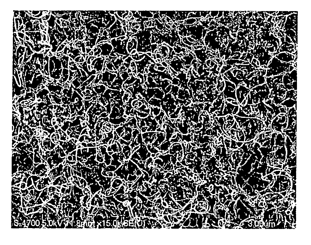
[0034]FIG. 1 is a flow chart showing the preparation procedure according to the preferred embodiment. Initially, in step 102, a fixed amount of nanotube was dispersed in a toluene solution containing a nonionic surfactant. The solution was contained in an ultrasonic bath in step 104 to obtain a dispersed nanotube suspension, which was then combined with the polystyrene solution in toluene, provided in step 106, to mix them in step 108. The final mixture was further sonicated to give a black-colored stable solution with no detectable solid precipitation. The resulting solution was sprayed onto a flat plate in step 110 by a micro-sprayer and dried at room temperature. Subsequently, the dried film was thermally cured in an air-circulating oven in step 112 to remove toluene from the thin film. A seri...


PUM

PropertyMeasurementUnit
Dielectric polarization enthalpyaaaaaaaaaa
Electrical conductivityaaaaaaaaaa
Concentrationaaaaaaaaaa

Abstract

An electromagnetic interference (EMI) shielding material includes a matrix of a dielectric or partially conducting polymer, such as foamed polystyrene, with carbon nanotubes or other nanostructures dispersed therein in sufficient concentration to make the material electrically conducting. The composite is formed by dispersing the nanotube material in a solvent in which the dielectric or partially conducting polymer is soluble and mixing the resulting suspension with the dielectric or partially conducting polymer. A foaming agent can be added to produce a lightweight foamed material. An organometallic compound can be added to enhance the conductivity further by decomposition into a metal phase.

Description

REFERENCE TO RELATED APPLICATION[0001]The present application claims the benefit of U.S. Provisional Patent Application No. 60 / 751,705, filed Dec. 19, 2005, whose disclosure is hereby incorporated by reference in its entirety into the present disclosure.STATEMENT OF GOVERNMENT INTEREST[0002]The work leading to the present invention was supported by National Science Foundation Grant No. GA10510 and NASA Grant No. GG10747. The government has certain rights in the invention.FIELD OF THE INVENTION[0003]The present invention is directed to electromagnetic interference (EMI) shielding materials and more particularly to such materials comprising nanotubes, nanofibers, or nanostructures dispersed in dielectric or partially conducting hosts. The present invention is further directed to a method for preparing such shielding materials and various applications.DESCRIPTION OF RELATED ART[0004]Electrically conducting polymer-matrix composites have gained popularity for electromagnetic interferenc...

Claims


Application Information

Patent Timeline
IPC IPC(8): H05K1/02C08K3/04C08J9/228C08K5/56B05D3/00
CPCH01B1/24H01C17/0652H01G9/058Y10T29/49117H01M4/137H01M4/364H01M4/587H01M4/133H01G11/22Y02E60/10
Inventor GUPTA, MOOL C.YANG, YONGLAIDUDLEY, KENNETH L.LAWRENCE, ROLAND W.
Owner NASA
Learn More