Process for producing membrane/electrode assembly for polymer electrolyte fuel cell and process for producing polymer electrolyte fuel cell

a technology of electrolyte fuel cell and electrolyte, which is applied in the direction of fuel cells, sustainable manufacturing/processing, climate sustainability, etc., can solve the problems of deterioration of gas diffusion properties, insufficient adhesion between gas diffusion layer and catalyst layer, and inability to meet the requirements of the conventional process. achieve the effect of wide current density range and high output voltag

Inactive Publication Date: 2010-01-07
PANASONIC CORP +1
View PDF6 Cites 19 Cited by
  • Summary
  • Abstract
  • Description
  • Claims
  • Application Information

AI Technical Summary

Benefits of technology

[0026]The present invention makes it feasible to produce the membrane / electrode assembly for the polymer electrolyte fuel cell and the polymer electrolyte fuel cell capable of achieving a high output voltage in a wide current density range.

Problems solved by technology

However, the membrane / electrode assemblies obtained by the conventional processes are not necessarily satisfactory in properties such as the gas diffusion property, electrical conductivity, water repellency and durability of the electrodes.
For example, the membrane / electrode assembly obtained by the above process (1) has a problem that adhesion between the gas diffusion layer and the catalyst layer is insufficient.
Furthermore, the membrane / electrode assembly obtained by the above process (2) has a problem that pores of the gas diffusion layer are clogged in forming the catalyst layer, for example, to deteriorate the gas diffusion property.
Moreover, the membrane / electrode assembly obtained by the above process (3) has a problem that the catalyst and gas diffusion layers are deformed by pressure in hot pressing, for example, to deteriorate the gas diffusion property.
In addition, these processes also have a problem of production cost because materials used for the gas diffusion layer are expensive.
Furthermore, the conventional polymer electrolyte fuel cells using such membrane / electrode assemblies fail to have sufficiently satisfactory properties, and, especially, it is difficult to obtain a high output voltage in a wide current density range.

Method used


Image

  • Process for producing membrane/electrode assembly for polymer electrolyte fuel cell and process for producing polymer electrolyte fuel cell
  • Process for producing membrane/electrode assembly for polymer electrolyte fuel cell and process for producing polymer electrolyte fuel cell

Examples


first embodiment

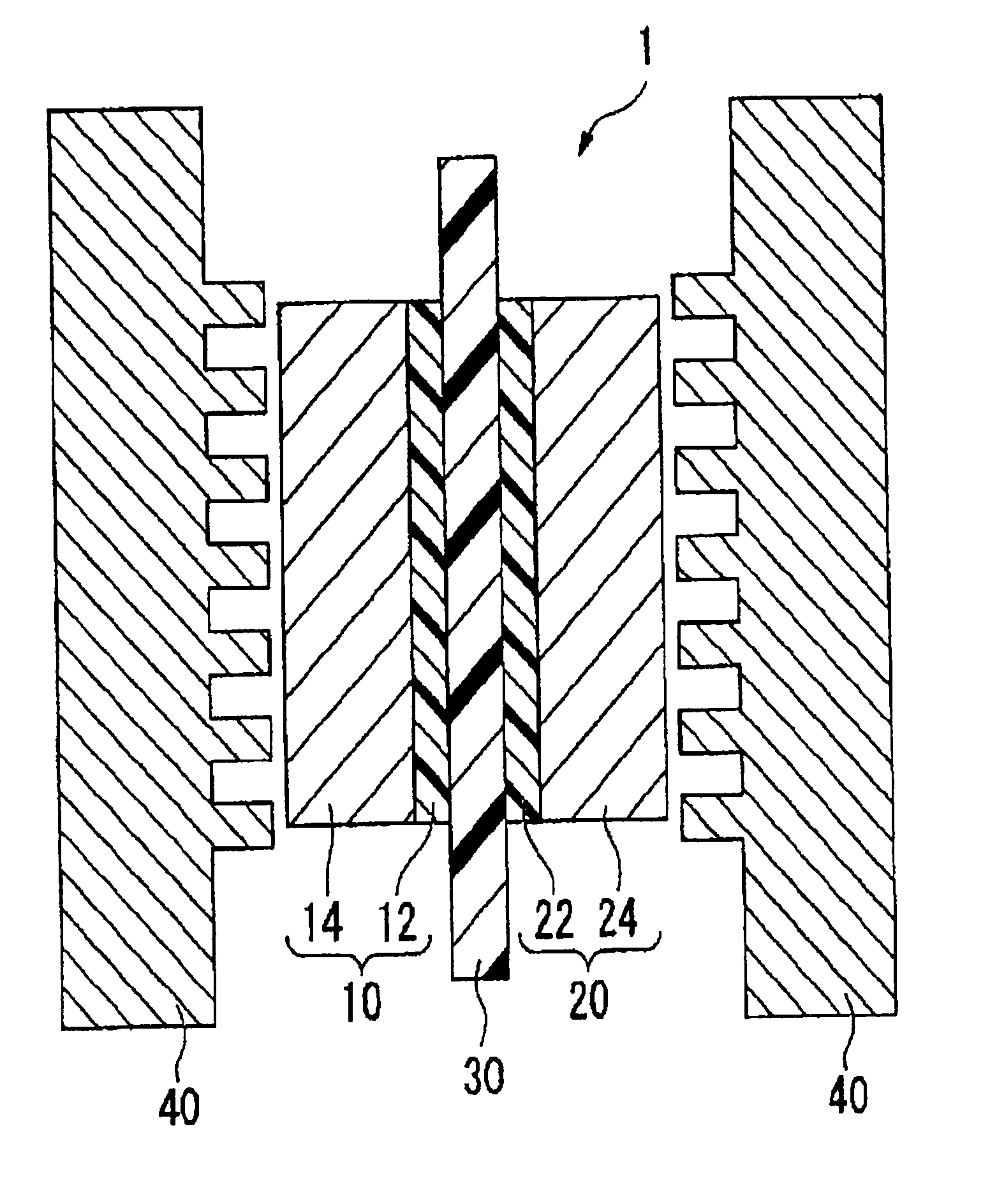
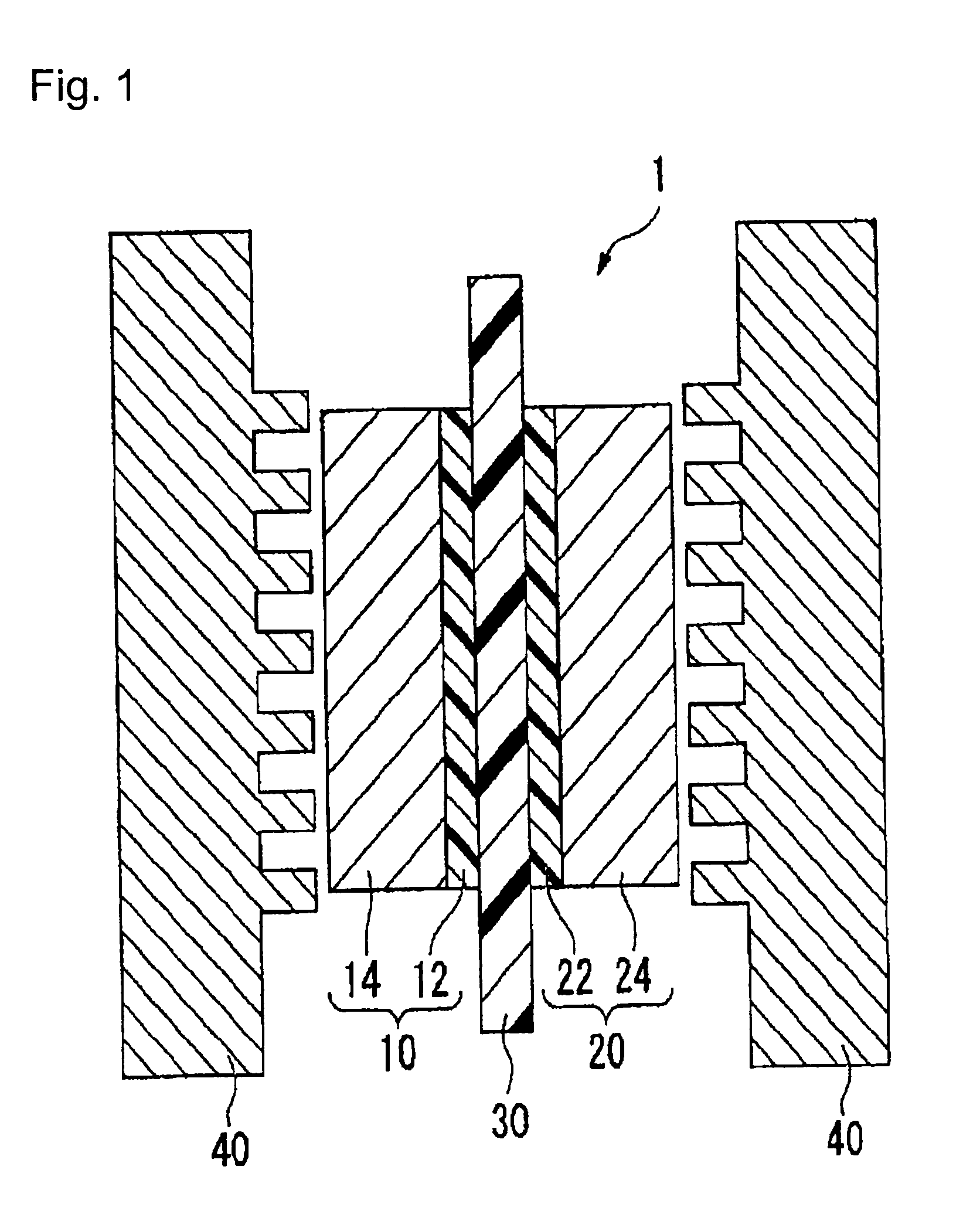
[0033]FIG. 1 is a schematic cross-sectional drawing of the polymer electrolyte fuel cell using the membrane / electrode assembly 1 produced in the present embodiment.

[0034]The membrane / electrode assembly 1 is composed of the anode 10, cathode 20 and polymer electrolyte membrane 30 disposed between them. The anode 10 is composed of the catalyst layer 12 and the carbon fiber layer 14, and the catalyst layer 12 is adjacent to the polymer electrolyte membrane 30. The cathode 20 is composed of the catalyst layer 22 and the carbon fiber layer 24, and the catalyst layer 22 is adjacent to the polymer electrolyte membrane 30.

[0035]The membrane / electrode assembly 1 is disposed between two separators 40 each having a gas channel formed on a surface thereof to constitute the polymer electrolyte fuel cell. At that time, the carbon fiber layer 14 of the anode 10 and the carbon fiber layer 24 of the cathode 20, which are the outermost layers in the membrane / electrode assembly 1, are adjacent to the ...

second embodiment

[0105]In the present embodiment, only the cathode 20 is prepared in the same manner as in the first embodiment, and the catalyst layer 22 of the cathode 20 is bonded to the electrolyte membrane 30.

[0106]The anode 10 in the membrane / electrode assembly 1 obtained in the present embodiment has the catalyst layer 12 adjacent to the electrolyte membrane 30 and the ordinary gas diffusion layer, instead of the carbon fiber layer 14, is adjacent to the surface of the catalyst layer which is not adjacent to the electrolyte membrane 30.

[0107]Namely, the outermost layer on the cathode 20 side is the carbon fiber layer and the outermost layer on the anode side is the ordinary gas diffusion layer in the membrane / electrode assembly prepared in the present embodiment.

[0108]In the present embodiment, a method for forming the anode 10 on the surface of the electrolyte membrane 30 may be, for example, a method wherein the catalyst layer 12 is directly formed on the surface of the electrolyte membrane...

third embodiment

[0112]In the present embodiment, only the anode 10 is prepared in the same manner as in the first embodiment, and the catalyst layer 12 of the anode 10 is bonded to the electrolyte membrane 30.

[0113]The present embodiment can be carried out in the same manner as in the second embodiment except that the methods of forming the anode 10 and the cathode 20 are opposite.

[0114]In the second embodiment and third embodiment, the ordinary gas diffusion layer is provided on the outermost layer of the membrane / electrode assembly on the side where no carbon fiber layer exists (i.e., on the outermost layer on the anode 10 side in the second embodiment, or on the outermost layer on the cathode 20 side in the third embodiment), but the present invention is by no means restricted to these examples. For example, the anode 10 in the second embodiment may be comprised of only the catalyst layer 12, or the cathode 20 of the third embodiment may be comprised of only the catalyst layer 22. In this case, ...


PUM

PropertyMeasurementUnit
thicknessaaaaaaaaaa
diameteraaaaaaaaaa
temperatureaaaaaaaaaa

Abstract

Provided are a process for producing a membrane/electrode assembly for a polymer electrolyte fuel cell and a process for producing a polymer electrolyte fuel cell, capable of achieving a high output voltage in a wide current density range.
At least one of an anode and a cathode in a membrane/electrode assembly for a polymer electrolyte fuel cell is formed through a catalyst layer forming step of applying a first coating fluid containing a catalyst and an ion exchange resin, onto a substrate to form a catalyst layer; a gas diffusion layer forming step of applying a second coating fluid containing carbon fibers and an ion exchange resin, onto the catalyst layer to form a gas diffusion layer to serve as an outermost layer of the membrane/electrode assembly for the polymer electrolyte fuel cell; and a peeling step of peeling the substrate off from the catalyst layer. The membrane/electrode assembly for the polymer electrolyte fuel cell is disposed between two separators each having a gas channel formed on a surface thereof so that surfaces of the outermost layers are adjacent to the respective separators, whereby the gas diffusion layer is adjacent to the separator.

Description

TECHNICAL FIELD[0001]The present invention relates to a process for producing a membrane / electrode assembly for a polymer electrolyte fuel cell and a process for producing a polymer electrolyte fuel cell.BACKGROUND ART[0002]Attention has been drawn to fuel cells using hydrogen and oxygen, as a power generating system which presents substantially no adverse effects on the global environment because in principle, its reaction product is water only. Among them, in recent years, a polymer electrolyte fuel cell using a proton conducting ion exchange membrane (polymer electrolyte membrane) as an electrolyte is expected to be useful for in-vehicle power sources, since its operation temperature is low, its output density is high and it can be downsized.[0003]The polymer electrolyte fuel cell comprises a membrane / electrode assembly having electrodes (an anode (fuel electrode) and a cathode (air electrode)) disposed on both sides of a polymer electrolyte membrane; and separators having a gas ...

Claims


Application Information

Patent Timeline
Patent Type & Authority Applications(United States)
IPC IPC(8): H01M8/00
CPCH01M8/1004Y02E60/521H01M2008/1095Y02E60/50Y02P70/50
Inventor TANUMA, TOSHIHIRO
Owner PANASONIC CORP
Why Eureka
Try Eureka