Co2 capture using solar thermal energy

a technology of solar thermal energy and solar energy, applied in the field of solar energy, can solve the problems of reducing the electrical power output by around 20%, relatively low partial pressure, and relatively high step energy consumption, and achieve the effect of effectively utilizing solar energy as a source of additional energy

Inactive Publication Date: 2010-01-14
COMMONWEALTH SCI & IND RES ORG
View PDF3 Cites 41 Cited by
  • Summary
  • Abstract
  • Description
  • Claims
  • Application Information

AI Technical Summary

Benefits of technology

[0010]It is a further object of the invention, at least in one or more aspects, to effectively empl

Problems solved by technology

The main disadvantage of this process is that the CO2 partial pressure is relatively low (compared to the two alternative approaches mentioned above), which necessitates the use of CO2 selective solvents.
The regeneration of these solvents releases an essentially pure CO2 stream, b

Method used


Image

  • Co2 capture using solar thermal energy
  • Co2 capture using solar thermal energy
  • Co2 capture using solar thermal energy

Examples


Embodiment Construction

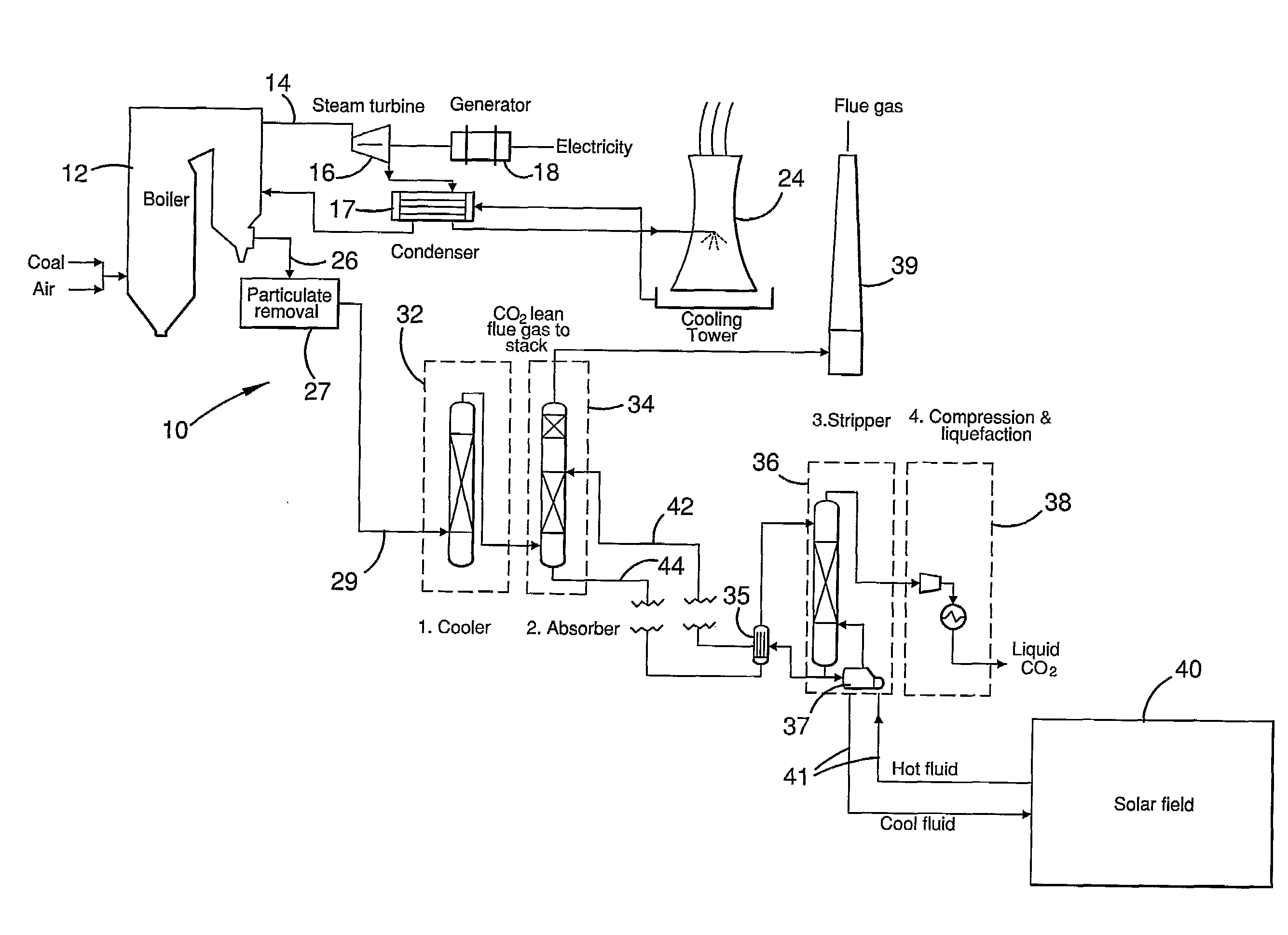
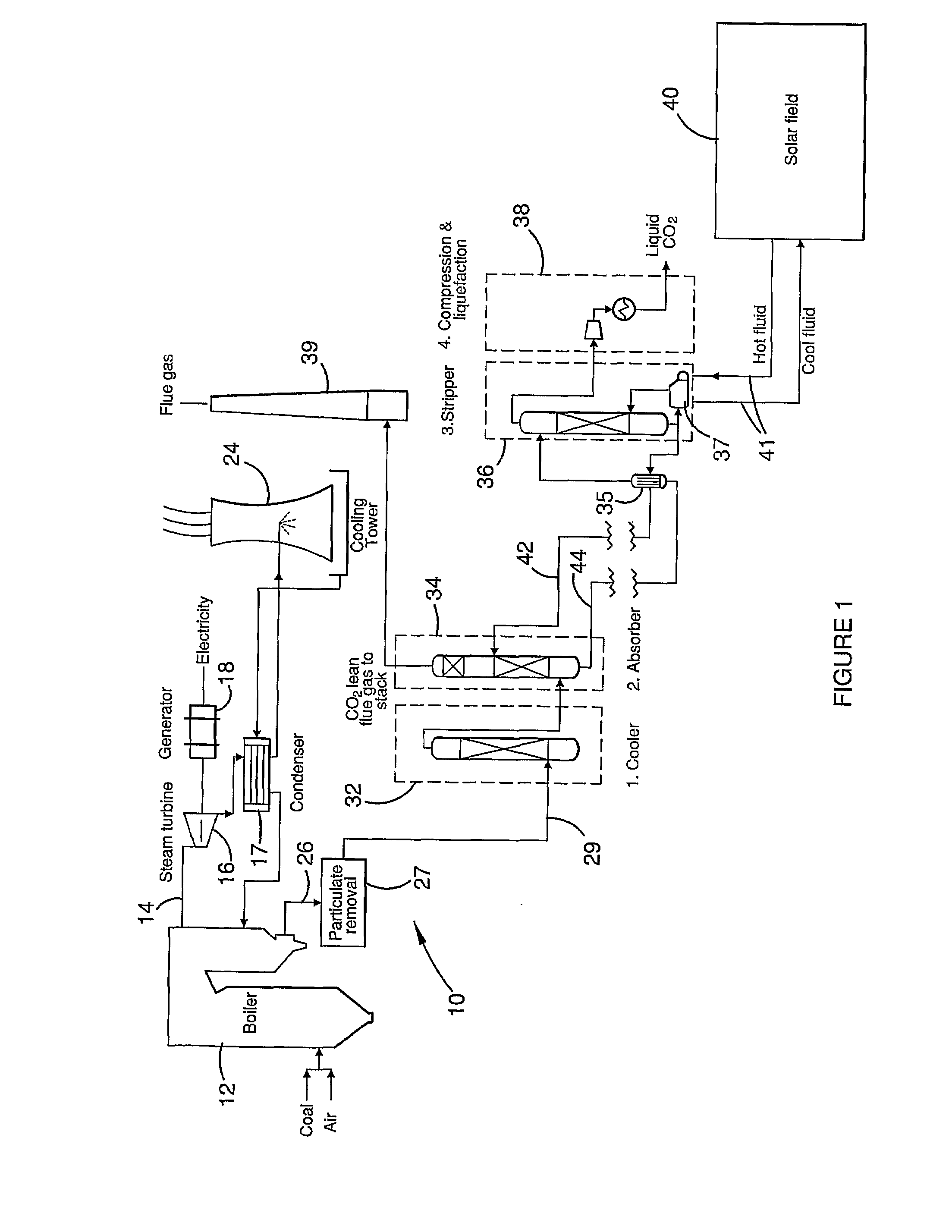
[0059]FIG. 1 depicts the essentials of a coal-fired power plant 10. Coal and air are delivered to a large scale boiler system 12 which heats large volumes of water to generate steam 14 for driving a steam turbine 16. Turbine 16 in turn powers a generator 18 that produces electricity as its output. The steam recovered from turbine 16 passes through a condenser 17 associated with a cooling tower 24, for recycling to the boiler. Flue gases 26 from boiler 12 are treated (at 27) to remove most particulates and other contaminants such as SO2 and SO3, and then passed at 29 to a four-stage plant for post-combustion capture of carbon dioxide. At stage 1, indicated at 32, the cleaned flue gases are cooled to a temperature suitable for efficient absorption of CO2 from the gases by a suitable solvent system. These solvents are also at times referred to as sorbents. At stage 2, comprising absorption station 34, the cleaned and cooled flue gases are scrubbed by contact with such a solvent system,...


PUM

PropertyMeasurementUnit
Energyaaaaaaaaaa
Solar energyaaaaaaaaaa

Abstract

At an absorber station, CO2 is absorbed from a gas stream into a suitable solvent whereby to convert the solvent into a CO2-enriched medium, which is conveyed to a desorber station, typically nearer to a solar energy field than to the absorber station. Working fluid, heated in the solar energy field by insolation, is employed to effect desorption of CO2 from the CO2-enriched medium, whereby to produce separate CO2 and regenerated solvent streams. The regenerated solvent stream is recycled to the absorber station. The CO2-enriched medium and/or the regenerated solvent stream may be selectively accumulated so as to respectively optimise the timing and rate of absorption and desorption of CO2 and/or to provide a storage of solar energy.

Description

FIELD OF THE INVENTION[0001]This invention relates generally to the use of solar energy for the recovery of carbon dioxide from gas streams. The invention has particular application to CO2 recovery from flue gases generated by coal- and gas-fired power plants or from process gases in a wide variety of industrial processes including steel plants, smelters, cement kilns and calciners. The term “process gases” refer to gas streams fed to or from a process, and embraces, e.g. syngas feed to an industrial furnace, and blast furnace gas in a steel plant.BACKGROUND OF THE INVENTION[0002]There is rapidly growing pressure for stationary sources of CO2 emissions such as power stations, to make step reductions in greenhouse gas (GHG) emissions through 1) capturing the CO2 formed from the process, and 2) storing the CO2 by various geological means. Most involve injecting CO2 in a supercritical or “liquefied” state into deep aquifers, coal seams and adjacent strata, or at depth in the ocean, or ...

Claims


Application Information

Patent Timeline
IPC IPC(8): B01D53/14B01D53/18F24J2/34C01B32/50F24S90/00
CPCB01D53/1425B01D53/1475B01D2256/22F24J2/04F28D20/003Y02P10/32Y02E10/44Y02E60/142Y02E70/30Y02P10/132Y02C10/06F24S10/00Y02E60/14Y02P10/122Y02P20/133Y02C20/40B01D53/14B01D53/18
Inventor WIBBERLEY, LOUIS
Owner COMMONWEALTH SCI & IND RES ORG
Why Eureka
Try Eureka